|
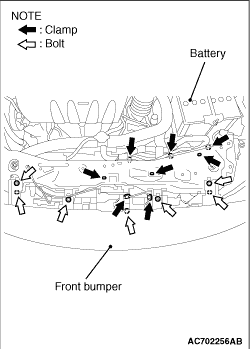
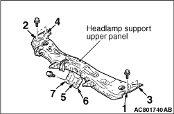
Remove the harness clamps and bolts shown in the illustration, and remove the headlamp
support upper panel.
|
|
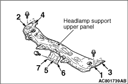
1.Install the mounting bolts of headlamp support upper panel in the order shown in the illustration.
|

|
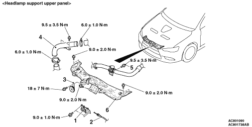
2.After installing the headlamp support upper panel, tighten the bolts shown in the illustration
to the specified torques.
|
|
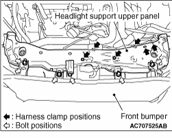
Remove the harness clamps and bolts shown in the illustration, and remove the headlamp
support upper panel.
|
|
1.Install the mounting bolts of headlamp support upper panel in the order shown in the illustration.
|

|
2.After installing the headlamp support upper panel, tighten the bolts shown in the illustration
to the specified torques.
|