|
|
Use M.U.T.-III to diagnose the CAN bus lines.
|
|
|
Q.
Is the check result normal?
|
|
|
 Repair the CAN bus line (Refer to GROUP 54C - Troubleshooting Repair the CAN bus line (Refer to GROUP 54C - Troubleshooting  ). ).
|
|
|
|
|
|
(1)Connect the negative battery terminal.
|
|
|
(2)After erasing the diagnosis code memory, check the diagnosis code again.
|
|
|
(3)Disconnect the negative battery terminal.
|
|
|
Q.
Is the diagnosis code No. B1206 set?
|
|
|
Intermittent malfunction (Refer to GROUP 00 - How to Use Troubleshooting/Inspection Service Points - How to Cope with Intermittent Malfunction ).
|
|
|
|
|
|
(1)It is checked whether instrument centre panel is normal (Refer to ).
|
|
|
Q.
Is the check result normal?
|
|
|
Replace instrument centre panel (Refer to GROUP 52A - Instrument Centre Panel ).
|
|
|
|
|
|
(1)Disconnect the negative battery terminal.
|

|
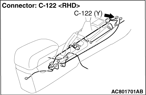
(2)While pushing the part "A" indicated in the figure of the harness side connector, turn the lock lever to the direction of the arrow to release the lock lever, and disconnect the C-122 SRS-ECU connector.
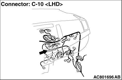
(3)Disconnect the C-10 instrument centre panel connector.
(4)Take the measurements below at the C-122 and C-10 wiring harness side connectors.
- Continuity between C-122 SRS-ECU connector terminal No. 18 and C-10 instrument centre panel connector terminal No. 11
OK: Continuity (less than 2 Ω)
Q.
Is the check result normal?
 Go to Step 5. Go to Step 5.
Repair the wiring harnesses between the C-122 SRS-ECU connector terminal No. 18 and the C-10 instrument centre panel connector terminal No. 11.
|
|
|
(1)Disconnect the C-10 instrument centre panel connector.
|
|
|
(2)Connect the negative battery terminal.
|
|
|
(4)Measure the voltage between the C-10 harness side connector terminal No. 8 and the body earth.
OK: Battery voltage
|
|
|
Q.
Is the check result normal?
|
|
|
Repair the wiring harness between the C-317 ETACS-ECU connector terminal No. 5 and the C-10 instrument centre panel connector terminal No. 8.
|
|
|
|
|
|
Q.
Is the diagnosis code No. B1206 set?
|
|
|
Replace SRS-ECU (Refer to ).
|
|
|
|
|
|
Intermittent malfunction (Refer to GROUP 00 - How to Use Troubleshooting/Inspection Service Points - How to Cope with Intermittent Malfunction ).
|
|
|
|