|
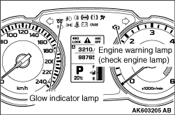
If an abnormality occurs in any of the following items related to the unit injection engine
control system, the engine warning lamp or glow indicator lamp will illuminate.
If the lamp remains illuminated or if the lamp illuminates while the engine is running,
check the diagnosis code output.
|
|
|
Refer to  , Inspection Chart For Diagnosis Code. , Inspection Chart For Diagnosis Code.
|
|
|
Refer to , GROUP 00 - How to Use Troubleshooting/Inspection
Service Points - Diagnosis Function.
|
|
|
1.Carry out inspection by means of the data list and the actuator test function, if
there is an abnormality, check and repair the chassis harness and components.
|
|
|
2.After repairing, re-check using the M.U.T.-III and check that the abnormal input and
output have returned to normal as a result of the repairs.
|
|
|
3.Erase the diagnosis code memory.
|
|
|
4.Remove the M.U.T.-III, and then start the engine again and carry out a road test to
confirm that the problem has disappeared.
|
|
|
When the engine-ECU detects a malfunction and stores a diagnosis code, it also stores
a current status of the engine. This function is called "Freeze frame data". By analyzing this "Freeze
frame" data with the M.U.T.-III, an effective troubleshooting can be preformed. The freeze frame
data shows the items selected from the list shown below in accordance with the diagnosis code.
|