|
|
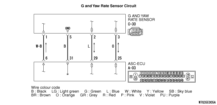
- ASC-ECU supplies power to the G and yaw rate sensor at the terminal No.1.
- The G and yaw rate sensor outputs the signal to ASC-ECU via the special CAN bus lines.
|
|
|
This diagnosis code is set if any malfunction below is found:
|
|
|
Code No.C2114
- When the power supply voltage applied from ASC-ECU to the G and yaw rate sensor is not within the standard value range (low)
|
|
|
Code No.C2115
- When the power supply voltage applied from ASC-ECU to the G and yaw rate sensor is not within the standard value range (high)
|
|
|
- Damaged wiring harness and connectors
- G and yaw rate sensor malfunction
- ASC-ECU malfunction
|
|
|
Use M.U.T.-III to diagnose the CAN bus lines.
|
|
|
Q.
Is the check result normal?
|
|
|
 Repair the CAN bus lines (Refer to GROUP 54C - CAN Bus Diagnosis table Repair the CAN bus lines (Refer to GROUP 54C - CAN Bus Diagnosis table  ). On completion, go to Step 2. ). On completion, go to Step 2.
|
|
|
|
|
|
Q.
Are the diagnosis codes No. C2114 or C2115 set?
|
|
|
This diagnosis is complete.
|
|
|
|
|
|
Check that the G and yaw rate sensor is installed correctly.
|
|
|
Q.
Is the check result normal?
|
|
|
Reinstall the G and yaw rate sensor correctly (Refer to ), and then go to Step 12.
|
|
|
|
|
|
(1)Do not disconnect the connector.
|
|
|
(2)Turn the ignition switch to the ON position.
|
|
|
(3)Measure the voltage between the terminal No.1 and the body earth for back probing.
OK: Approximately battery voltage
|
|
|
Q.
Is the check result normal?
|
|
|
Q.
Is the check result normal?
|
|
|
Repair the defective connector, and then go to Step 12.
|
|
|
|
|
|
- Check the open circuit in power supply circuit.
|
|
|
Q.
Is the check result normal?
|
|
|
Repair the wiring harness, and then go to Step 12.
|
|
|
|
|
|
(1)Disconnect the connector, and measure at the wiring harness-side connector.
|
|
|
(2)Resistance between the terminal No.5 and the body earth
OK: Continuity exists (2 Ω or less)
|
|
|
Q.
Is the check result normal?
|
|
|
Q.
Is the check result normal?
|
|
|
Repair the defective connector, and then go to Step 12.
|
|
|
|
|
|
- Check the earth wires for open circuit.
|
|
|
Q.
Is the check result normal?
|
|
|
Repair the wiring harness, and then go to Step 12.
|
|
|
|
|
|
Check the following service data (Refer to ).
|
|
|
- Item 08: Lateral G-sensor
- Item 09: G sensor
- Item 12: Yaw rate sensor
|
|
|
Q.
Is the check result normal?
|
|
|
Replace the G and yaw rate sensor (Refer to ), and then go to Step 12.
|
|
|
|
|
|
Q.
Are the diagnosis codes No.C2114 or C2115 set?
|
|
|
 Replace the ASC-ECU (Refer to ), and then go to Step 12. Replace the ASC-ECU (Refer to ), and then go to Step 12.
|
|
|
|
|
|
Intermittent malfunction (Refer to GROUP 00 - How to Cope with Intermittent Malfunction ).
|
|
|
|
|
|
Q.
Are the diagnosis codes No.C2114 or C2115 set?
|
|
|
This diagnosis is complete.
|
|
|
|