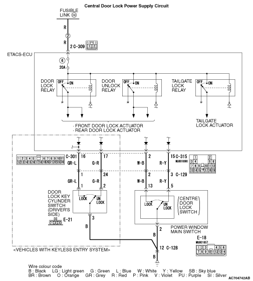
INSPECTION PROCEDURE A-1: Central Door Locking System does not work at All.
| caution | Before replacing the ECU, ensure that the power supply circuit, the earth circuit and the communication circuit are normal. |
OPERATION
COMMENTS ON TROUBLE SYMPTOM
PROBABLE CAUSES
- Malfunction of the front door lock actuator (driver’s side)
- Malfunction of power window main switch (centre door lock switch)
- Malfunction of ETACS-ECU
- Damaged wiring harness and connectors
DIAGNOSTIC PROCEDURE
STEP 1. M.U.T.-III diagnosis code
Q.
Is the diagnosis code set?


STEP 2. M.U.T.-III data list
|
Q.
Is the check result normal?
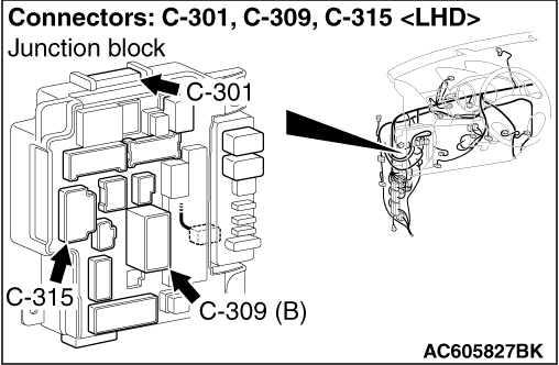
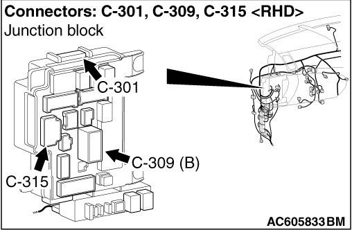
STEP 3. Connector check: C-309 ETACS-ECU connector
Q.
Is the check result normal?
STEP 4. Check the wiring harness between C-309 ETACS-ECU connector terminal No. 2 and fusible link (38).
- Check the power supply line for open circuit and short circuit.
Q.
Is the check result normal?
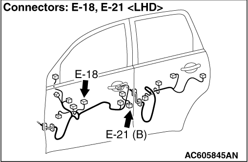
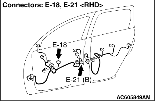
STEP 5. Connector check: E-18 power window main switch connector
Q.
Is the check result normal?
STEP 6. Power window main switch check
Q.
Is the check result normal?
STEP 7. Resistance measurement at E-18 power window main switch connector
| (1)Disconnect the connector, and measure at the wiring harness side. |
| (2)Measure the resistance between the E-18 power window main switch connector terminal No. 2 and the body earth. OK: Continuity (less than 2Ω) |
Q.
Is the check result normal?
STEP 8. Check of the wiring harness between the E-18 power window main switch connector terminal No. 2 and the body earth
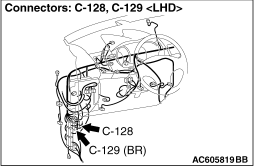
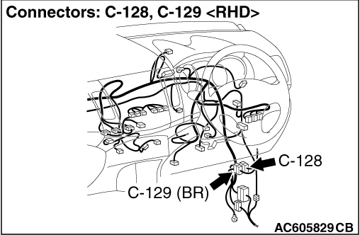
| note | Prior to the wiring harness inspection, check the C-128 intermediate connector, and repair if necessary. |
- Check the earth wires for open circuit.
Q.
Is the check result normal?
STEP 9. Connector check: C-301, C-315 ETACS-ECU connector
Q.
Is the check result normal?
STEP 10. Check of the wiring harness between the C-301 ETACS-ECU connector terminal No. 2 and the E-18 power window main switch connector terminal No. 13, the C-315 ETACS-ECU connector terminal No. 15 and the E-18 power window main switch connector terminal No. 5
| note | Prior to the wiring harness inspection, check the C-129 intermediate connector, and repair if necessary. |
- Check the input/output line for open circuit.
Q.
Is the check result normal?

STEP 11. Connector check: E-21 door lock key cylinder switch (driver’s side) connector
Q.
Is the check result normal?
STEP 12. Door lock key cylinder switch (driver’s side) check
Q.
Is the check result normal?
STEP 13. Resistance measurement at E-21 door lock key cylinder switch (driver’s side) connector
| (1)Disconnect the connector, and measure at the wiring harness side. |
| (2)Measure the resistance between the E-21 door lock key cylinder switch (driver’s side) connector terminal No. 3 and the body earth. OK: Continuity (less than 2Ω) |
Q.
Is the check result normal?
STEP 14 Check of the wiring harness between the E-21 door lock key cylinder switch (driver’s side) connector terminal No. 3 and the body earth
| note | Prior to the wiring harness inspection, check the C-128 intermediate connector, and repair if necessary. |
- Check the earth wires for open circuit.
Q.
Is the check result normal?
STEP 15. Connector check: C-301 ETACS-ECU connector
Q.
Is the check result normal?
STEP 16. Check of the wiring harness between the C-301 ETACS-ECU connector terminal No. 16 and the E-21 door lock key cylinder switch (driver’s side) connector terminal No. 1, the C-301 ETACS-ECU connector terminal No. 17 and the E-21 door lock key cylinder switch (driver’s side) connector terminal No. 2
| note | Prior to the wiring harness inspection, check the C-129 intermediate connector, and repair if necessary. |
- Check the input/output line for open circuit.
Q.
Is the check result normal?
STEP 17. Retest the system.
Q.
Is the check result normal?