|
|
Q.
Is the check result normal?
|
|
|
 Repair the defective connector. Repair the defective connector.
|
|
|
|
|
|
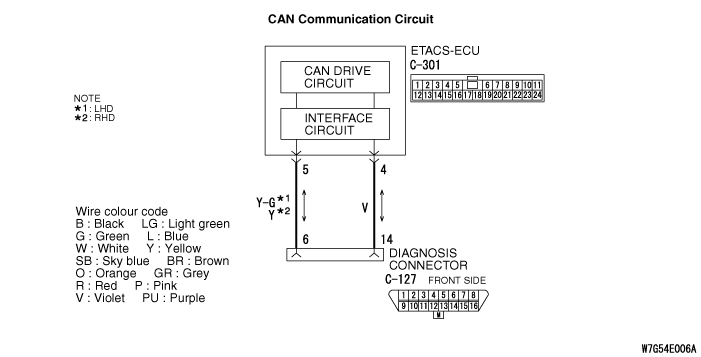
(1)Disconnect the M.U.T.-III and ETACS-ECU connector, and check the wiring harness.
|
|
|
(2)Check that there is continuity between C-127 diagnosis connector terminal No.6 and ETACS-ECU connector terminal No.5 <CAN_H>
OK: Continuity exists (2 Ω or less)
|
|
|
(3)Check that there is continuity between C-127 diagnosis connector terminal No.14 and ETACS-ECU connector terminal No.4 <CAN_L>
OK: Continuity exists (2 Ω or less)
|
|
|
Q.
Is the check result normal?
|
|
|
Repair the wiring harness.
|
|
|
|
|
|
(1)Disconnect the M.U.T.-III and the ETACS-ECU connector, and measure at the wiring harness side.
|
|
|
(2)Measure the resistance between C-127 diagnosis connector terminal No.6 and body earth. <CAN_H>
OK: 1 kΩ or more
|
|
|
(3)Measure the resistance between C-127 diagnosis connector terminal No.14 and body earth. <CAN_L>
OK: 1 kΩ or more
|
|
|
Q.
Is the check result normal?
|
|
|
Repair the wiring harness.
|
|
|
|
|
|
(1)Disconnect the M.U.T.-III and the ETACS-ECU connector, and measure at the wiring harness side.
|
|
|
(2)Measure the voltage between C-127 diagnosis connector terminal No.6 and body earth. <CAN_H>
OK: 5 V or less
|
|
|
(3)Measure the voltage between C-127 diagnosis connector terminal No.14 and body earth. <CAN_L>
OK: 5 V or less
|
|
|
Q.
Is the check result normal?
|
|
|
Repair the wiring harness.
|
|
|
|
|
|
(1)Disconnect the M.U.T.-III and the ETACS-ECU connector, and check that there is continuity at the harness side.
|
|
|
(2)Check that there is continuity between C-127 diagnosis connector terminal Nos.6 and 14.
OK: No continuity
|
|
|
Q.
Is the check result normal?
|
|
|
Repair the wiring harness.
|
|
|
|
|
|
Diagnose the CAN bus line, and check that normal condition is displayed.
|
|
|
Q.
Is the check result normal?
|
|
|
 The trouble can be an intermittent malfunction (Refer to GROUP 00 - How to use Troubleshooting/inspection Service Points - How to Cope with Intermittent Malfunction The trouble can be an intermittent malfunction (Refer to GROUP 00 - How to use Troubleshooting/inspection Service Points - How to Cope with Intermittent Malfunction  ). ).
|
|
|
|