|
|
Q.
Is the check result normal?
|
|
|
YES <vehicles without ASC> : Go to Step 3. : Go to Step 3.
|
|
|
|
|
|
YES <vehicles with ASC> : Go to Step 2.
|
|
|
|
|
|
NO (connector is not normal.) : Repair the defective connector.
|
|
|
|
|
|
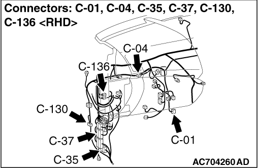
(1)Disconnect joint connector (CAN2), and check that there is continuity at the harness
side.
|
|
|
(2)Check that there is continuity between C-04 joint connector (CAN2) terminal Nos.4
and 15.
OK: No continuity
|
|
|
Q.
Is the check result normal?
|
|
|
(1)Disconnect joint connector (CAN2), and check that there is continuity at the harness
side.
|
|
|
(2)Check that there is continuity between C-04 joint connector terminal Nos.5 and
16.
OK: No continuity
|
|
|
Q.
Is the check result normal?
|
|
|
(1)Disconnect joint connector (CAN3), and check that there is continuity at the harness
side.
|
|
|
(2)Check that there is continuity between C-01 joint connector terminal Nos.4 and
15.
OK: No continuity
|
|
|
Q.
Is the check result normal?
|
|
|
YES <A/T, CVT> : Go to Step 5.
|
|
|
|
|
|
YES <M/T> : Go to Step 6.
|
|
|
|
|
|
(1)Disconnect joint connector (CAN3), and check that there is continuity at the harness
side.
|
|
|
(2)Check that there is continuity between C-01 joint connector terminal Nos.7 and
20.
OK: No continuity
|
|
|
Q.
Is the check result normal?
|
|
|
(1)Disconnect joint connector (CAN3), and check that there is continuity at the harness
side.
|
|
|
(2)Check that there is continuity between C-01 joint connector terminal Nos.6 and
19.
OK: No continuity
|
|
|
Q.
Is the check result normal?
|
|
|
(1)Disconnect joint connector (CAN2), and check that there is continuity at the harness
side.
|
|
|
(2)Check that there is continuity between C-04 joint connector terminal Nos.6 and
19 <LHD> or 7 and 20 <RHD>.
OK: No continuity
|
|
|
Q.
Is the check result normal?
|
|
|
 Check C-37 intermediate connector, and repair if necessary. If the intermediate
connector is in good condition, repair the wiring harness between C-04 joint connector (CAN2)
and C-01 joint connector (CAN3). Check C-37 intermediate connector, and repair if necessary. If the intermediate
connector is in good condition, repair the wiring harness between C-04 joint connector (CAN2)
and C-01 joint connector (CAN3).
|
|
|
|
|
|
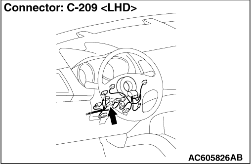
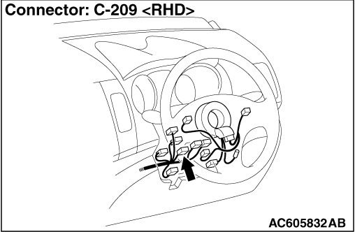
Disconnect C-209 steering wheel sensor connector, and diagnose the CAN bus line.
|
|
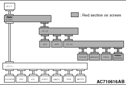
OK: The display of the M.U.T.-III is as shown in the figure.
Q.
Does M.U.T.-III screen correspond to the illustration?
Repair the wiring harness between C-209 steering wheel sensor connector and C-04
joint connector (CAN2).
 Check the steering wheel sensor connector, and repair if necessary. If the steering
wheel sensor connector is in good condition, replace the steering wheel sensor. Check the steering wheel sensor connector, and repair if necessary. If the steering
wheel sensor connector is in good condition, replace the steering wheel sensor.
|
|
|
Disconnect C-130 4WD-ECU connector, and diagnose the CAN bus line.
|
|
OK: The display of the M.U.T.-III is as shown in the figure.
Q.
Does M.U.T.-III screen correspond to the illustration?
Check C-35 intermediate connector, and repair if necessary. If the intermediate
connector is in good condition, repair the wiring harness between C-130 4WD-ECU connector and
C-04 joint connector (CAN2).
Check the 4WD-ECU connector, and repair if necessary. If the 4WD-ECU connector
is in good condition, replace the 4WD-ECU.
|
|
|
Disconnect B-06 engine-ECU connector <2000> or B-18 engine-ECU connector <2200>
or B-30 engine-ECU connector <2400, 3000>, and diagnose the CAN bus line.
|
|
OK: The display of the M.U.T.-III is as shown in the figure.
Q.
Does M.U.T.-III screen correspond to the illustration?
Repair the wiring harness between B-06 engine-ECU connector <2000> or B-18
engine-ECU connector <2200> or B-30 engine-ECU connector <2400, 3000> and C-01 joint
connector (CAN3).
Check the engine-ECU connector, and repair if necessary. If the engine-ECU connector
is in good condition, replace the engine-ECU.
|
|
|
Disconnect C-136 CVT-ECU connector <CVT> or C-138 A/T-ECU connector <A/T>, and
diagnose the CAN bus line.
|
|
OK: The display of the M.U.T.-III is as shown in the figure.
Q.
Does M.U.T.-III screen correspond to the illustration?
Repair the wiring harness between C-136 CVT-ECU connector <CVT> or C-138 A/T-ECU
connector <A/T> and C-01 joint connector (CAN3).
Check the CVT-ECU connector <CVT> or A/T-ECU connector <A/T>, and repair
if necessary. If the CVT-ECU connector <CVT> or A/T-ECU connector <A/T> is in good condition,
replace the CVT-ECU <CVT> or A/T-ECU <A/T>.
|
|
|
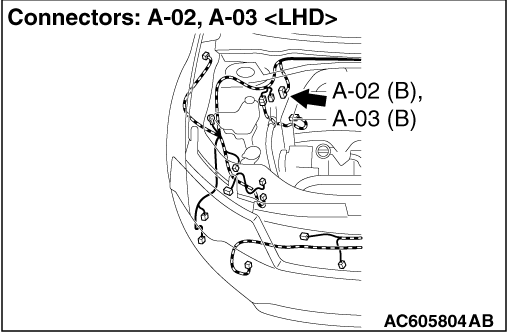
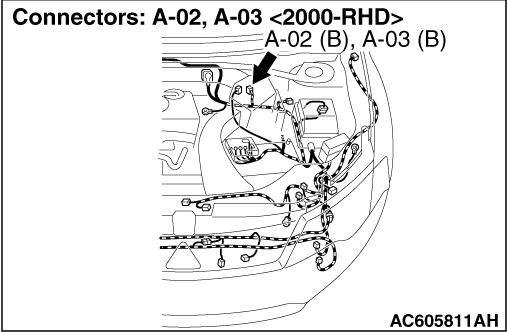
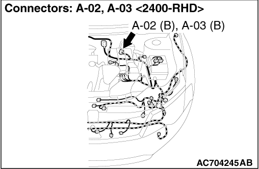
Disconnect A-02 ABS-ECU connector <vehicles without ASC> or A-03 ASC-ECU connector <vehicles
with ASC>, and diagnose the CAN bus line.
|
|
OK: The display of the M.U.T.-III is as shown in the figure.
Q.
Does M.U.T.-III screen correspond to the illustration?
Repair the wiring harness between A-02 ABS-ECU connector <vehicles without
ASC> or A-03 ASC-ECU connector <vehicles with ASC> and C-01 joint connector (CAN3).
Check the ABS-ECU <vehicles without ASC> or ASC-ECU <vehicles with ASC>
connector, and repair if necessary. If the ABS-ECU <vehicles without ASC> or ASC-ECU <vehicles
with ASC> connector is in good condition, replace the ABS-ECU <vehicles without ASC> or
ASC-ECU <vehicles with ASC>.
|
|
|
(1)Disconnect the ETACS-ECU connector and the joint connector (CAN2), and check that
there is continuity at the harness side.
|
|
|
(2)Check that there is continuity between C-04 joint connector terminal Nos.6 and
19 <LHD> or 7 and 20 <RHD>.
OK: No continuity
|
|
|
Q.
Is the check result normal?
|
|
|
Repair the wiring harness between C-301 ETACS-ECU connector and C-04 joint connector
(CAN2).
|
|
|
|
|
|
Diagnose the CAN bus line, and check that normal condition is displayed.
|
|
|
Q.
Is the check result normal?
|
|
|
The trouble can be an intermittent malfunction (Refer to GROUP 00 - How
to use Troubleshooting/inspection Service Points - How to Cope with Intermittent
Malfunction  ). ).
|
|
|
|
|
|
Check the ETACS-ECU connector, and repair if necessary. If the ETACS-ECU connector
is in good condition, replace the ETACS-ECU.
|
|
|
|