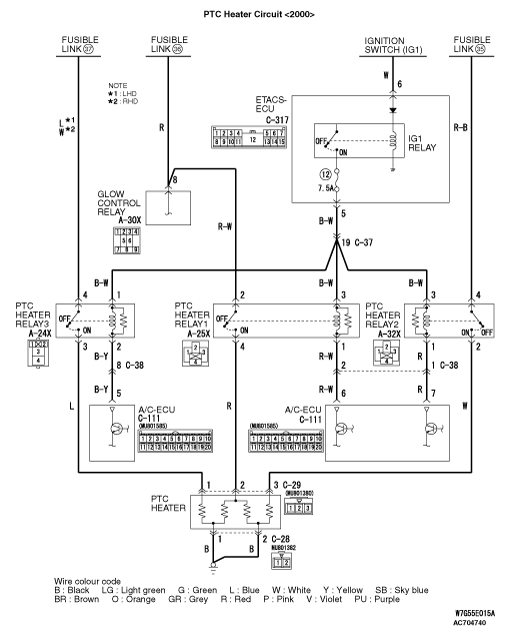
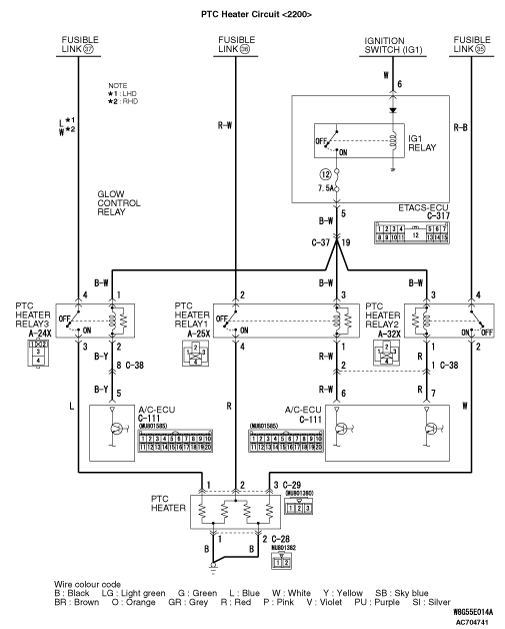
INSPECTION PROCEDURE 17: The PTC heater does not work.

|
|
COMMENTS ON TROUBLE SYMPTOM
|
|
|
With the engine and blower motor being operated, if the PTC heater does not operate by setting the heater control to MAX HOT at the coolant temperature of 75 °C or lower, the PTC heater, PTC heater relay, A/C-ECU or its circuit system may be faulty.
|
|
|
- Malfunction of the PTC heater
- Malfunction of the PTC heater relay1
- Malfunction of the PTC heater relay2
- Malfunction of the PTC heater relay3
- Damaged the wiring harness or connectors
- Malfunction of the A/C-ECU
|
|
|
STEP 1. M.U.T.-III diagnosis code
|
|
|
Check that the air conditioner has not set a diagnosis code.
|
|
|
Q.
Is the diagnosis code set?
|
|
|
 Carry out the diagnosis code procedures. Refer to Carry out the diagnosis code procedures. Refer to  . .
|
|
|
|
|
|
 Go to Step 2. Go to Step 2.
|
|
|
|
|
|
STEP 2. M.U.T.-III other system’s diagnosis code
|
|
|
Check that the ETACS-ECU has not set a diagnosis code.
|
|
|
Q.
Is the diagnosis code set?
|
|
|
Carry out the diagnosis code procedures . Refer to GROUP 54A, ETACS-ECU .
|
|
|
|
|
|
Go to Step 3.
|
|
|
|
|
|
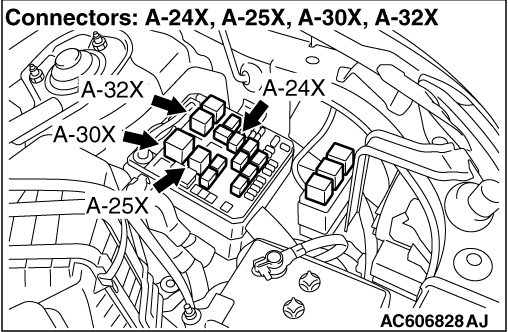
STEP 3. Connector check: A-25X PTC heater relay1 connector, A-32X PTC heater relay2 connector and A-24X PTC heater relay3 connector
|
|
|
Q.
Is the check result normal?
|
|
|
Go to Step 4.
|
|
|
|
|
|
Repair the connector concerned.
|
|
|
|
|
|
STEP 4. Check the PTC heater relay1, 2 and 3.
|
|
|
Refer to .
|
|
|
Q.
Is the check result normal?
|
|
|
Go to Step 5.
|
|
|
|
|
|
Replace the PTC heater relay1, 2 or 3.
|
|
|
|
|
|
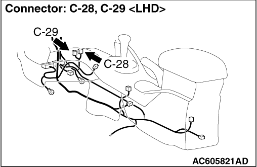
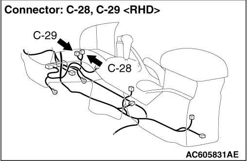
STEP 5. Connector check: C-29 PTC heater connector and C-111 A/C-ECU connector
|
|
|
Q.
Is the check result normal?
|
|
|
Repair the connector concerned.
|
|
|
|
|
|
STEP 6. Measure the voltage at C-29 PTC heater connector.
|
|
|
(1)Disconnect the connector, and measure at the wiring harness side.
|
|
|
(3)Disconnect A/C-ECU connector C-111 and earth terminal 6.
|
|
|
(4)Voltage between terminal 1 and body earth
OK: Battery voltage
|
|
|
Q.
Is the check result normal?
|
|
|
Go to Step 13.
|
|
|
|
|
|
Go to Step 7.
|
|
|
|
|
|
STEP 7. Measure the voltage at A-25X PTC heater relay1 connector.
|
|
|
(1)Remove the relay, and measure at the relay side.
|
|
|
(2)Voltage between terminal 2 and body earth
OK: Battery voltage
|
|
|
Q.
Is the check result normal?
|
|
|
Go to Step 9.
|
|
|
|
|
|
Go to Step 8.
|
|
|
|
|
|
STEP 8. Check the wiring harness between A-25X PTC heater relay1 connector terminal No. 2 and fusible link (36) connector.
|
|
|
| note |
Prior to the wiring harness inspection, check glow control relay connector A-30X, and repair if necessary. <2000>
|
|
|
|
- Check the power supply line for open circuit.
|
|
|
Q.
Is the check result normal?
|
|
|
Intermittent malfunction (Refer to GROUP 00 - How to Use Troubleshooting/Inspection Service Points - How to Cope with Intermittent Malfunction ).
|
|
|
|
|
|
Repair the wiring harness.
|
|
|
|
|
|
STEP 9. Measure the voltage at A-25X PTC heater relay1 connector.
|
|
|
(1)Remove the relay, and measure at the relay side.
|
|
|
(2)Turn the ignition switch to the "ON" earth position.
|
|
|
(3)Voltage between terminal 3 and body earth
OK: Battery voltage
|
|
|
Q.
Is the check result normal?
|
|
|
Go to Step 11.
|
|
|
|
|
|
Go to Step 10.
|
|
|
|
|
|
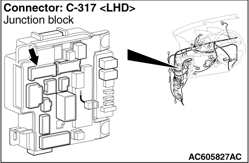
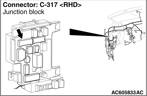
STEP 10. Check the wiring harness between A-25X PTC heater relay1 connector terminal No. 3 and C-317 ETACS-ECU connector terminal No. 6.
|
|
|
| note |
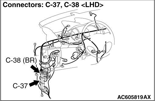
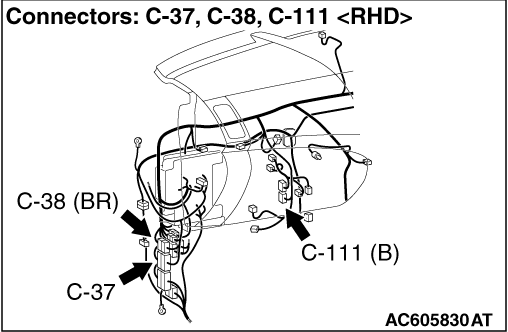
Prior to the wiring harness inspection, check intermediate connector C-37, and repair if necessary.
|
|
|
|
- Check the power supply line for open circuit.
|
|
|
Q.
Is the check result normal?
|
|
|
Intermittent malfunction (Refer to GROUP 00 - How to Use Troubleshooting/Inspection Service Points - How to Cope with Intermittent Malfunction ).
|
|
|
|
|
|
Repair the wiring harness.
|
|
|
|
|
|
STEP 11. Check the wiring harness wires between C-29 PTC heater connector terminal No. 2 and A-25X PTC heater relay1 connector terminal No. 4.
|
|
|
- Check the power supply line for open circuit.
|
|
|
Q.
Is the check result normal?
|
|
|
Go to Step 12.
|
|
|
|
|
|
Repair the wiring harness.
|
|
|
|
|
|
STEP 12. Check the wiring harness between A-25X PTC heater relay1 connector terminal No. 1 and C-111 A/C-ECU connector terminal No. 6.
|
|
|
| note |
Prior to the wiring harness inspection, check intermediate connector C-38, and repair if necessary.
|
|
|
|
- Check the power supply line for open circuit.
|
|
|
Q.
Is the check result normal?
|
|
|
Intermittent malfunction (Refer to GROUP 00 - How to Use Troubleshooting/Inspection Service Points - How to Cope with Intermittent Malfunction ).
|
|
|
|
|
|
Repair the wiring harness.
|
|
|
|
|
|
STEP 13. Measure the voltage at C-29 PTC heater connector.
|
|
|
(1)Disconnect the connector, and measure at the wiring harness side.
|
|
|
(3)Disconnect A/C-ECU connector C-111 and earth terminal 7.
|
|
|
(4)Voltage between terminal 3 and body earth
OK: Battery voltage
|
|
|
Q.
Is the check result normal?
|
|
|
Go to Step 20.
|
|
|
|
|
|
Go to Step 14.
|
|
|
|
|
|
STEP 14. Measure the voltage at A-32X PTC heater relay2 connector.
|
|
|
(1)Remove the relay, and measure at the relay side.
|
|
|
(2)Voltage between terminal 4 and body earth
OK: Battery voltage
|
|
|
Q.
Is the check result normal?
|
|
|
Go to Step 16.
|
|
|
|
|
|
Go to Step 15.
|
|
|
|
|
|
STEP 15. Check the wiring harness between A-32X PTC heater relay2 connector terminal No. 4 and fusible link (36) connector.
|
|
|
- Check the power supply line for open circuit.
|
|
|
Q.
Is the check result normal?
|
|
|
Intermittent malfunction (Refer to GROUP 00 - How to Use Troubleshooting/Inspection Service Points - How to Cope with Intermittent Malfunction ).
|
|
|
|
|
|
Repair the wiring harness.
|
|
|
|
|
|
STEP 16. Measure the voltage at A-32X PTC heater relay2 connector.
|
|
|
(1)Remove the relay, and measure at the relay side.
|
|
|
(2)Turn the ignition switch to the "ON" earth position.
|
|
|
(3)Voltage between terminal 3 and body earth
OK: Battery voltage
|
|
|
Q.
Is the check result normal?
|
|
|
Go to Step 18.
|
|
|
|
|
|
Go to Step 17.
|
|
|
|
|
|
STEP 17. Check the wiring harness between A-32X PTC heater relay2 connector terminal No. 3 and C-317 ETACS-ECU connector terminal No. 6.
|
|
|
| note |
Prior to the wiring harness inspection, check intermediate connector C-37, and repair if necessary.
|
|
|
|
- Check the power supply line for open circuit.
|
|
|
Q.
Is the check result normal?
|
|
|
Intermittent malfunction (Refer to GROUP 00 - How to Use Troubleshooting/Inspection Service Points - How to Cope with Intermittent Malfunction ).
|
|
|
|
|
|
Repair the wiring harness.
|
|
|
|
|
|
STEP 18. Check the wiring harness wires between C-29 PTC heater connector terminal No. 3 and A-32X PTC heater relay2 connector terminal No. 2.
|
|
|
- Check the power supply line for open circuit.
|
|
|
Q.
Is the check result normal?
|
|
|
Go to Step 19.
|
|
|
|
|
|
Repair the wiring harness.
|
|
|
|
|
|
STEP 19. Check the wiring harness between A-32X PTC heater relay2 connector terminal No. 1 and C-111 A/C-ECU connector terminal No. 7.
|
|
|
| note |
Prior to the wiring harness inspection, check intermediate connector C-38, and repair if necessary.
|
|
|
|
- Check the power supply line for open circuit.
|
|
|
Q.
Is the check result normal?
|
|
|
Intermittent malfunction (Refer to GROUP 00 - How to Use Troubleshooting/Inspection Service Points - How to Cope with Intermittent Malfunction ).
|
|
|
|
|
|
Repair the wiring harness.
|
|
|
|
|
|
STEP 20. Measure the voltage at C-29 PTC heater connector.
|
|
|
(1)Disconnect the connector, and measure at the wiring harness side.
|
|
|
(3)Disconnect A/C-ECU connector C-111 and earth terminal 7.
|
|
|
(4)Voltage between terminal 1 and body earth
OK: Battery voltage
|
|
|
Q.
Is the check result normal?
|
|
|
Go to Step 27.
|
|
|
|
|
|
Go to Step 21.
|
|
|
|
|
|
STEP 21. Measure the voltage at A-24X PTC heater relay3 connector.
|
|
|
(1)Remove the relay, and measure at the relay side.
|
|
|
(2)Voltage between terminal 4 and body earth
OK: Battery voltage
|
|
|
Q.
Is the check result normal?
|
|
|
Go to Step 23.
|
|
|
|
|
|
Go to Step 22.
|
|
|
|
|
|
STEP 22. Check the wiring harness between A-24X PTC heater relay3 connector terminal No. 4 and fusible link (36) connector.
|
|
|
- Check the power supply line for open circuit.
|
|
|
Q.
Is the check result normal?
|
|
|
Intermittent malfunction (Refer to GROUP 00 - How to Use Troubleshooting/Inspection Service Points - How to Cope with Intermittent Malfunction ).
|
|
|
|
|
|
Repair the wiring harness.
|
|
|
|
|
|
STEP 23. Measure the voltage at A-24X PTC heater relay3 connector.
|
|
|
(1)Remove the relay, and measure at the relay side.
|
|
|
(2)Turn the ignition switch to the "ON" earth position.
|
|
|
(3)Voltage between terminal 1 and body earth
OK: Battery voltage
|
|
|
Q.
Is the check result normal?
|
|
|
Go to Step 25.
|
|
|
|
|
|
Go to Step 24.
|
|
|
|
|
|
STEP 24. Check the wiring harness between A-24X PTC heater relay3 connector terminal No. 1 and C-317 ETACS-ECU connector terminal No. 5.
|
|
|
| note |
Prior to the wiring harness inspection, check intermediate connector C-37, and repair if necessary.
|
|
|
|
- Check the power supply line for open circuit.
|
|
|
Q.
Is the check result normal?
|
|
|
Intermittent malfunction (Refer to GROUP 00 - How to Use Troubleshooting/Inspection Service Points - How to Cope with Intermittent Malfunction ).
|
|
|
|
|
|
Repair the wiring harness.
|
|
|
|
|
|
STEP 25. Check the wiring harness wires between A-29 PTC heater connector terminal No. 3 and A-24X PTC heater relay3 connector terminal No. 3.
|
|
|
- Check the power supply line for open circuit.
|
|
|
Q.
Is the check result normal?
|
|
|
Go to Step 26.
|
|
|
|
|
|
Repair the wiring harness.
|
|
|
|
|
|
STEP 26. Check the wiring harness between A-24X PTC heater relay3 connector terminal No. 2 and C-111 A/C-ECU connector terminal No. 5.
|
|
|
| note |
Prior to the wiring harness inspection, check intermediate connector C-38, and repair if necessary.
|
|
|
|
- Check the power supply line for open circuit.
|
|
|
Q.
Is the check result normal?
|
|
|
Intermittent malfunction (Refer to GROUP 00 - How to Use Troubleshooting/Inspection Service Points - How to Cope with Intermittent Malfunction ).
|
|
|
|
|
|
Repair the wiring harness.
|
|
|
|
|
|
STEP 27. Connector check: C-28 PTC heater connector
|
|
|
Q.
Is the check result normal?
|
|
|
Go to Step 28.
|
|
|
|
|
|
Repair the connector.
|
|
|
|
|
|
STEP 28. Resistance measurement at C-28 PTC heater connector.
|
|
|
(1)Disconnect the connector, and measure at the wiring harness side.
|
|
|
(2)Continuity between terminal 1, 2 and body earth.
OK: Continuity (Less than 2 ohms)
|
|
|
Q.
Is the check result normal?
|
|
|
Go to Step 30.
|
|
|
|
|
|
Go to Step 29.
|
|
|
|
|
|
STEP 29. Check the wiring harness between C-28 PTC heater connector (terminals 1 and 2) and body earth.
|
|
|
- Check the PTC heater earth line for open circuit.
|
|
|
Q.
Is the check result normal?
|
|
|
Intermittent malfunction (Refer to GROUP 00 - How to Use Troubleshooting/Inspection Service Points - How to Cope with Intermittent Malfunction ).
|
|
|
|
|
|
Repair the wiring harness.
|
|
|
|
|
|
STEP 30. Check the PTC heater.
|
|
|
Refer to .
|
|
|
Q.
Is the check result normal?
|
|
|
Replace the A/C-ECU.
|
|
|
|
|
|
Replace the PTC heater.
|
|
|
|