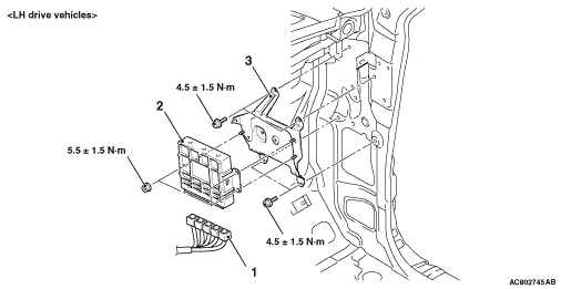
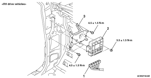
REMOVAL AND INSTALLATION


caution
  • When the engine-A/T-ECU replacement is performed, always refer to GROUP 54A - Immobilizer System, Troubleshooting, Encrypted Code Registration Criteria Table <3800> .
  • After the engine-A/T-ECU replacement, idling speed may be unstable because the MPI engine learning is not completed. To make it stable, let the system learn the idling (Refer to GROUP 00, Precautions before Service - Learning Procedure for Idling in MPI Engine ).
Pre-removal Operation
  • Front Scuff Plate Outer and Cowl Side Trim Removal (Refer to GROUP 52A - Trim ) <Passenger’s Side>.
  • Passenger’s Side Lower Cover and Glove Box Assembly Removal (Refer to GROUP 52A - Instrument panel assembly ).

Post-installation Operation
  • Passenger’s Side Lower Cover and Glove Box Assembly Installation (Refer to GROUP 52A - Instrument panel assembly ).
  • Front Scuff Plate Outer and Cowl Side Trim Installation (Refer to GROUP 52A - Trim ) <Passenger’s Side>.


Removal steps

>>A<<
·
Initialisation operation (only at installation)


1.
Engine-A/T-ECU connector
<<A>>

2.
Engine-A/T-ECU
<<B>>

3.
ECU bracket

REMOVAL SERVICE POINTS


<<A>> ENGINE-A/T-ECU REMOVAL


1.Disconnect the wiring harness connectors installed to the front pillar to provide sufficient clearance for engine-A/T-ECU removal.
2.Remove the engine-A/T-ECU.

<<B>> ECU BRACKET REMOVAL


1.Disconnect the wiring harness connectors installed on the backside of the ECU bracket.
2.Remove the ECU bracket.

INSTALLATION SERVICE POINT


>>A<< INITIALISATION PROCEDURE


Turn the ignition switch on then off, and keep it off for at least 10 seconds.