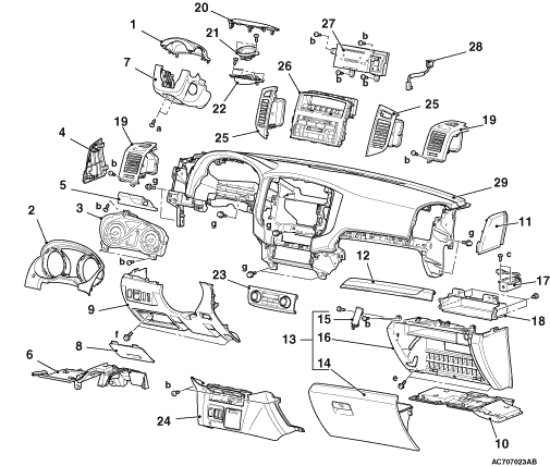
REMOVAL AND INSTALLATION
| Name |
Symbol |
Dimensions mm (screw diameter × screw length) |
Colour |
Shape |
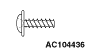
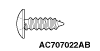
| Tapping screw |
a |
5 × 16 |
Black |
 |
| b |
5 × 16 |
- |
 |
|
| c |
5 × 14 |
- |
||
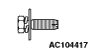
| Washer-assembled bolt |
d |
6 × 16 |
- |
 |
| e |
6 × 18 |
- |
||
| f |
5 × 18 |
- |
 |
|
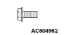
| Flange bolt |
g |
6 × 14 |
- |
 |
| caution |
|

 |
|
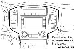
REMOVAL SERVICE POINT |
<<A>> CENTRE LOWER PANEL ASSEMBLY/CENTRE AIR OUTLET/CENTRE UPPER PANEL ASSEMBLY REMOVAL |
 |
|
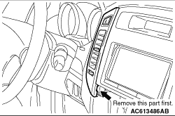 |
First remove the part shown in the figure when removing the centre air outlet. |
CLIP AND CLAW POSITIONS
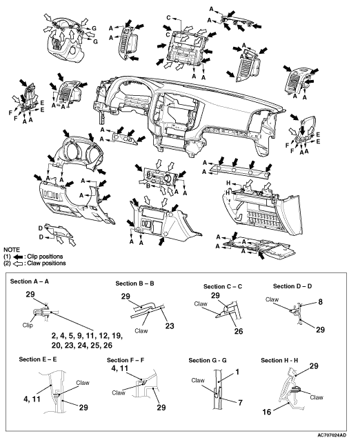
| note | Each number in the illustration indicates a part number. |