|
|
- Refer to Data List Reference Table
 . .
- Item 6: Manifold absolute pressure sensor
|
|
|
Q.
Is the check result normal?
|
|
|
 Intermittent malfunction (Refer to GROUP 00 -
How to Use Troubleshooting/Inspection
Service Points -
How to Cope with Intermittent Malfunctions -
How to Cope
with Intermittent Malfunctions ). Intermittent malfunction (Refer to GROUP 00 -
How to Use Troubleshooting/Inspection
Service Points -
How to Cope with Intermittent Malfunctions -
How to Cope
with Intermittent Malfunctions ).
|
|
|
|
|
|
- Check whether the vacuum hose is clogged between the manifold absolute pressure
sensor and the inlet manifold, which is caused by dirt and the hose folded. Also check the inside
inlet manifold and the nipple that can be possibly contaminated with dirt.
|
|
|
Q.
Is the check result normal?
|
|
|
Q.
Is the check result normal?
|
|
|
 Repair or replace the connector. Repair or replace the connector.
|
|
|
|
|
|
- Use special tool test harness (MB991709) to connect connector, and measure
at pick-up harness.
- Ignition switch: ON
- Voltage between terminal No. 1 and earth.
|
|
|
Q.
Is the check result normal?
|
|
|
Q.
Is the check result normal?
|
|
|
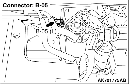
Check and repair harness between B-05 (terminal No.
1) manifold absolute pressure sensor connector and D-213 (terminal No. 72) engine-ECU connector.
- Check power supply line for damage.
|
|
|
|
|
|
Repair or replace the connector.
|
|
|
|
|
|
- Use special tool harness (MB991709) to connect connector, and measure at
pick-up harness.
- Ignition switch: ON
- Voltage between terminal No. 3 and earth.
|
|
|
Q.
Is the check result normal?
|
|
|
Q.
Is the check result normal?
|
|
|
Check and repair harness between B-05 (terminal No.
3) manifold absolute pressure sensor connector and D-213 (terminal No. 31) engine-ECU connector.
- Check earthing line for damage.
|
|
|
|
|
|
Repair or replace the connector.
|
|
|
|
|
|
- Use special tool harness (MB991709) to connect connector, and measure at
pick-up harness.
- Ignition switch: ON
- Voltage between terminal No. 2 and earth.
|
|
|
OK: The voltage should be 0.7 -
1.2 V. When the accelerator pedal is quickly
depressed from the idling state, the voltage temporarily rises.
|
|
|
Q.
Is the check result normal?
|
|
|
Replace the manifold absolute pressure sensor.
|
|
|
|
|
|
- Measure engine-ECU terminal voltage.
- Ignition switch: ON
- Voltage between terminal No. 37 and earth.
|
|
|
OK: The voltage should be 0.7 -
1.2 V. When the accelerator pedal is quickly
depressed from the idling state, the voltage temporarily rises.
|
|
|
Q.
Is the check result normal?
|
|
|
Check and repair harness between B-05 (terminal
No. 2) manifold absolute pressure sensor connector and D-213 (terminal No. 37) engine-ECU connector.
- Check output line for damage.
|
|
|
|
|
|
Q.
Is the check result normal?
|
|
|
Repair or replace the connector.
|
|
|
|
|
|
- Refer to Data List Reference Table .
- Item 6: Manifold absolute pressure sensor
|
|
|
Q.
Is the check result normal?
|
|
|
Intermittent malfunction (Refer to GROUP 00 -
How to Use Troubleshooting/Inspection
Service Points -
How to Cope with Intermittent Malfunctions ).
|
|
|
|
|
|
Replace the engine-ECU. When the engine-ECU is replaced, write the chassis number
(Refer to GROUP 00 -
Precautions Before Service -
How to Perform Chassis Number
Writing ). After replacing the engine-ECU, register the injector identification
code and learn fuel injection (Refer to GROUP 00 -
Precautions Before Service -
What
The Common Rail Engine Learns ). After registering the injector
identification code, the vehicle equipped with the closed type DPF carries out the forcible
DPF regeneration. (Refer to GROUP 17 -
Diesel Particulate Filter (DPF) System -
Forcible
DPF Regeneration ).
|
|
|
|