REMOVAL AND INSTALLATION


caution *:Indicates parts which should be temporary tightened, and then fully tightened with the vehicle on the ground in the unladen condition.
Pre-removal and Post-installation Operation
  • Removal and Installation of Under Cover (Refer to GROUP 51, Under Cover ).
  • Gear Oil Draining and Supplying (Refer to ).
  • Drive Shaft (RH) Removal and Installation (Refer to ).
  • Strut assembly (RH) Removal and Installation (Refer to GROUP 33, Shock absorber assembly ).


Removal steps
<<A>>
>>B<<
1.
Inner shaft


2.
Clip


3.
Collar


4.
Pin


5.
Actuator assembly


6.
Vacuum tank assembly


7.
Free wheel engage switch


8
Gasket

>>A<<
·
Loosening and tightening of differential mounting insulator bolt


·
Support the differential with a transmission jack


9.
Differential mounting bracket (RH)


10.
Breather hose


11.
Breather pipe


12.
Housing tube

REMOVAL SERVICE POINT


<<A>> INNER SHAFT REMOVAL


caution When pulling the inner shaft out from the front differential carrier, be careful that the spline part of the inner shaft does not damage the oil seal.

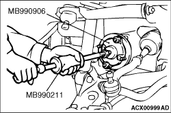
Pull the inner shaft from the Housing tube by using the following special tools.

  • Driveshaft attachment (MB990906)
  • Sliding hammer (MB990211)

INSTALLATION SERVICE POINTS


>>A<< DIFFERENTIAL MOUNTING INSULATOR BOLT TIGHTENING


caution Place the vehicle on the ground after temporarily tightening bolts to prevent bushing from twisting, then fully tighten the bolts in the unladen condition.

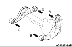
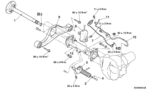
Tighten the bolts shown in the diagram to the specified torque in the order of A, B, C, D or A, C, B, D.
Tightening torque: 80 ± 10 N·m

>>B<< INNER SHAFT INSTALLATION


caution Be careful not to damage the lip of the dust seal and oil seal.