|
|
- The brake warning lamp illuminates or goes out by the transistor control
inside the ASTC-ECU. In this circuit, when the transistor is ON, the brake warning lamp goes
out. Even when the ASTC-ECU connector is connected improperly or the ASTC-ECU is disabled, the
brake warning lamp illuminates by the circuit in the meter.
- Other than the case when the system has malfunctioned, the ASTC-ECU illuminates
the brake warning lamp for approximately 3 seconds during the initial check with the ignition
switch being in the ON position.
- The brake warning lamp illuminates also in the cases when the parking brake is operated,
and when the brake fluid level is the specified value or less.
|
|
|
The most likely causes for this case are:
|
|
|
- The brake pad thickness is at the limit value or less.
- The brake fluid amount is at the "LOWER" level or lower.
- Poor adjustment of the parking brake lever
- Damaged wiring harness and connectors
- Parking brake switch malfunction
- Brake fluid level switch malfunction
- Malfunction of the combination meter
- The ASTC-ECU is defective.
|
|
|
Check that the brake fluid is filled up to the "MIN" level or higher.
|
|
|
Q.
Is the check result normal?
|
|
|
Refer to GROUP 35A - On-vehicle Service, Brake Pad Check  . .
|
|
|
Q.
Is the check result normal?
|
|
|
 Fill the brake fluid up to the "MAX" level. Then go to Step 15. Fill the brake fluid up to the "MAX" level. Then go to Step 15.
|
|
|
|
|
|
 Replace the brake pad. (Refer to GROUP 35A - On-vehicle Service, Disc
Brake Pad Check and Replacement <short wheelbase>, <long
wheelbase>.) Then go to Step 15. Replace the brake pad. (Refer to GROUP 35A - On-vehicle Service, Disc
Brake Pad Check and Replacement <short wheelbase>, <long
wheelbase>.) Then go to Step 15.
|
|
|
|
|
|
Refer to GROUP 35A - On-vehicle Service, Brake Fluid Level Switch Check .
|
|
|
Q.
Is the check result normal?
|
|
|
Replace the reservoir assembly. <Refer to GROUP 35A - Hydraulic
Brake Booster Assembly (HBB) .> Then go to Step 15.
|
|
|
|
|
|
Q.
Is the check result normal?
|
|
|
Repair the damaged connector.
|
|
|
|
|
|
Refer to GROUP 36 - On-vehicle Service .
|
|
|
Q.
Is the check result normal?
|
|
|
Adjust the parking brake lever stroke. (Refer to GROUP 36 - On-vehicle
Service .) Then go to Step 15.
|
|
|
|
|
|
Refer to GROUP 36 - On-vehicle Service .
|
|
|
Q.
Is the check result normal?
|
|
|
Replace the parking brake switch. (Refer to GROUP 36 - Parking Brake
Lever .) Then go to Step 15.
|
|
|
|
|
|
Q.
Is the check result normal?
|
|
|
Repair the damaged connector.
|
|
|
|
|
|
Q.
Is the check result normal?
|
|
|
Repair the damaged connector.
|
|
|
|
|
|
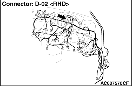
Check the wiring harness between D-21 parking brake switch connector terminal No. 1 and
D-02 combination meter connector terminal No. 37 for short circuit.
|
|
|
Q.
Is the check result normal?
|
|
|
Repair the wiring harness.
|
|
|
|
|
|
Check B-11 brake fluid level switch connector terminal No. 1 and D-02 combination meter
connector terminal No. 37 for short circuit.
|
|
|
Q.
Is the check result normal?
|
|
|
Repair the wiring harness.
|
|
|
|
|
|
Q.
Is the check result normal?
|
|
|
Repair the damaged connector.
|
|
|
|
|
|
Check the wiring harness between D-223 ASTC-ECU connector terminal No. 81 and D-02 combination
meter connector terminal No. 45 for short circuit.
|
|
|
Q.
Is the check result normal?
|
|
|
Repair the wiring harness.
|
|
|
|
|
|
Q.
After the ignition switch is turned to the "ON" position and the brake warning lamp
has illuminated for 3 seconds, does the lamp go out?
|
|
|
It can be assumed that this malfunction is intermittent. Refer to GROUP 00, How
to Use Troubleshooting/Inspection Service Points - How to Cope with Intermittent
Malfunction .
|
|
|
|
|
|
Replace the combination meter assembly. (Refer to GROUP 54A - Combination
Meter .) Then go to Step 14.
|
|
|
|
|
|
Q.
After the ignition switch is turned to the "ON" position and the brake warning lamp
has illuminated for 3 seconds, does the lamp go out?
|
|
|
The procedure is complete.
|
|
|
|
|
|
Replace the ASTC-ECU, and then go to Step 15.
|
|
|
|
|
|
Q.
After the ignition switch is turned to the "ON" position and the brake warning lamp
has illuminated for 3 seconds, does the lamp go out?
|
|
|
The procedure is complete.
|
|
|
|