|
|
Use the M.U.T.-III to diagnose the CAN bus lines.
|
|
|
Q.
Is the check result normal?
|
|
|
 Repair the CAN bus line (Refer to GROUP 54D, Diagnosis Repair the CAN bus line (Refer to GROUP 54D, Diagnosis  ). ).
|
|
|
|
|
|
Check again if the diagnosis code is set.
|
|
|
(1)Erase the diagnosis code.
|
|
|
(2)Ignition: "LOCK" (OFF) position to "ON"
|
|
|
(3)On completion, check that the diagnosis code is not reset.
|
|
|
Q.
Is the diagnosis code set?
|
|
|
There is an intermittent malfunction such as poor engaged connector(s) or open
circuit (Refer to GROUP 00, How to Cope with Intermittent Malfunction ).
|
|
|
|
|
|
Q.
Are connectors correctly engaged?
|
|
|
Engage the connectors correctly. Then go to Step 4.
|
|
|
|
|
|
(1)Disconnect the negative battery terminal.
|
|
|
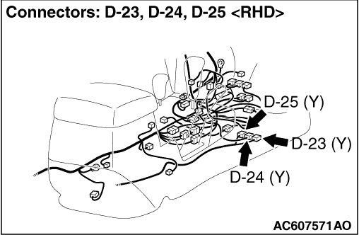
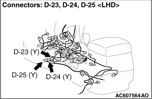
(2)Disconnect SRS-ECU harness side connectors D-23, D-24 and D-25.
|
|
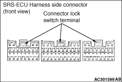
(3)Check the connector lock switch terminal inside the harness side connector for improper
contact or deformation.
Q.
Are the SRS-ECU harness side connector D-23, D-24 and D-25 in good condition?
 Erase the diagnosis code from memory, and check the diagnosis code. If diagnosis
code B1519 sets, replace the SRS-ECU (Refer to ). Erase the diagnosis code from memory, and check the diagnosis code. If diagnosis
code B1519 sets, replace the SRS-ECU (Refer to ).
Replace the SRS-ECU connector D-23, D-24 and D-25.
|