Inspection Procedure 2: No Sound is Heard. <Vehicles with Audio Amplifier: Short Wheelbase>
| caution | Whenever the multivision display is replaced, ensure that the power supply circuit and the earthing circuit are normal. (Check that the voltage is 10 V or more.) |
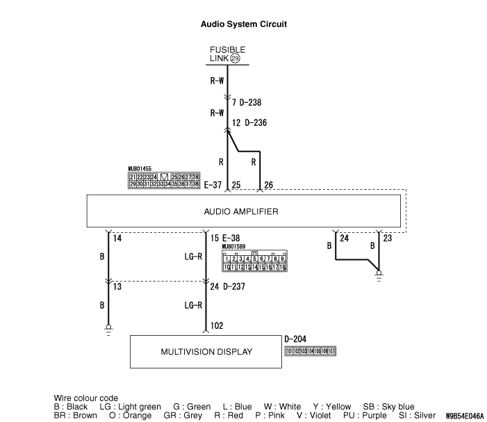
COMMENTS ON TROUBLE SYMPTOM
PROBABLE CAUSES
- Malfunctions of multivision display
- Malfunction of audio amplifier
- Damaged harness wires and connectors
DIAGNOSIS PROCEDURE
STEP 1. Check the multivision display operation.
Q.
Check the sources from which the sound is not output.


STEP 2. Check the service data log for the MMCS service mode.
| (1)Display the service data log for the MMCS service mode. (Refer to .) |
| (2)Check if the service data log for drive and HDD is displayed. |
Q.
Is the service data log displayed?

STEP 3. Perform "Network/Connect Line Check" in the MMCS service mode.
| (1)Display "Network/Connect Line Check" in the MMCS service mode. (Refer to .) |
| (2)Check if "DVD Drive OK" is displayed. |
| (3)Check if "HDD Drive OK" is displayed. |
Q.
Is the check result normal?

STEP 4. Connector check: E-37, E-38 audio amplifier connector
Q.
Is the check result normal?
STEP 5. Resistance measurement at E-37, E-38 audio amplifier connector
| (1)Disconnect the connector, and measure at the wiring harness side. |
| (2)Check the continuity between E-37 audio amplifier connector terminal No.23 and the body earth. OK: Continuity exists (2 Ω or less) |
| (3)Check the continuity between E-37 audio amplifier connector terminal No.24 and the body earth. OK: Continuity exists (2 Ω or less) |
| (4)Check the continuity between E-38 audio amplifier connector terminal No.14 and the body earth. OK: Continuity exists (2 Ω or less) |
Q.
Is the check result normal?
STEP 6. Check the harness wire between E-37 audio amplifier connector terminal No.23, 24 or E-38 audio amplifier connector terminal No.14 and the body earth
- Check the earth wires for open circuit.
Q.
Is the check result normal?
STEP 7. Voltage measurement at E-37 audio amplifier connector
| (1)Disconnect the connector, and measure at the wiring harness-side connector. |
| (2)Measure the voltage between E-37 audio amplifier connector terminal No.25 and the body earth OK: System voltage |
| (3)Measure the voltage between E-37 audio amplifier connector terminal No.26 and the body earth OK: System voltage |
Q.
Is the check result normal?
STEP 8. Check the harness wire between E-37 audio amplifier connector terminal No.25, 26 and fusible link (29).
- Check the power supply line for open circuit and short circuit.
| note | Prior to the wiring harness inspection, check intermediate connectors D-236 and D-238, and repair if necessary. |
Q.
Is the check result normal?
STEP 9. Connector check: D-204 multivision display connector
Q.
Is the check result normal?
STEP 10. Check the harness wire between D-204 multivision display connector terminal No.102 and E-38 audio amplifier connector No.15
- Check the communication lines for open circuit and short circuit.
| note | Prior to the wiring harness inspection, check intermediate connectors D-237, and repair if necessary. |
Q.
Is the check result normal?
STEP 11. Retest the system
Q.
Is the check result normal?
STEP 12. Retest the system
Q.
Is the check result normal?