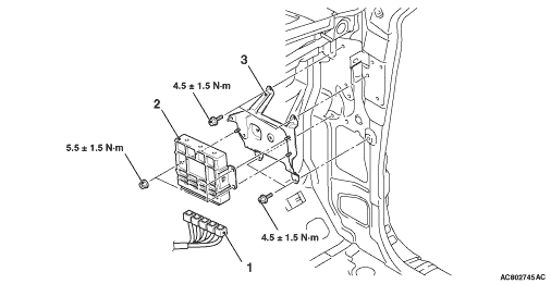
REMOVAL AND INSTALLATION


caution
  • When the engine-ECU <M/T> or engine-A/T-ECU <A/T> replacement is performed, always refer to GROUP 54A - Immobilizer System, On-vehicle Service, How to Register Key ID <3000, 3800> .
  • After the engine-ECU <M/T> or engine-A/T-ECU <A/T> replacement, idling speed may be unstable because the MPI engine learning is not completed. To make it stable, let the system learn the idling (Refer to GROUP 00, Precautions before Service - Learning Procedure for Idling in MPI Engine ).
Pre-removal Operation
  • Front Scuff Plate Outer and Cowl Side Trim Removal (Refer to GROUP 52A - Trim ) <Passenger’s Side>.
  • Passenger’s Side Lower Cover and Glove Box Assembly Removal (Refer to GROUP 52A - Instrument panel assembly ).

Post-installation Operation
  • Passenger’s Side Lower Cover and Glove Box Assembly Installation (Refer to GROUP 52A - Instrument panel assembly ).
  • Front Scuff Plate Outer and Cowl Side Trim Installation (Refer to GROUP 52A - Trim ) <Passenger’s Side>.


Engine-ECU <M/T> removal steps

>>A<<
·
Initialisation operation (only at installation)


1.
Engine-ECU connector connection
<<A>>

2.
Engine-ECU
<<B>>

3.
ECU bracket


Engine-A/T-ECU <A/T> removal steps

>>A<<
·
Initialisation operation (only at installation)


1.
Engine-A/T-ECU connector connection
<<A>>

2.
Engine-A/T-ECU
<<B>>

3.
ECU bracket

REMOVAL SERVICE POINTS


<<A>> ENGINE-ECU <M/T> OR ENGINE-A/T-ECU <A/T> REMOVAL


1.Disconnect the wiring harness connectors installed to the front pillar to provide sufficient clearance for engine-ECU <M/T> or engine-A/T-ECU <A/T> removal.
2.Remove the engine-ECU <M/T> or engine-A/T-ECU <A/T>.

<<B>> ECU BRACKET REMOVAL


1.Disconnect the wiring harness connectors installed on the backside of the ECU bracket.
2.Remove the ECU bracket.

INSTALLATION SERVICE POINT


>>A<< INITIALISATION PROCEDURE


Turn the ignition switch on then off, and keep it off for at least 10 seconds.