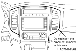
REMOVAL AND INSTALLATION


Name
Symbol
Dimensions mm (screw diameter × screw length)
Colour
Shape
Tapping screw
a
5 × 16
Black


b
5 × 16
-


c
5 × 14
-
Washer-assembled bolt
d
6 × 16
-


e
6 × 18
-
f
5 × 18
-


Flange bolt
g
6 × 12
-


caution
  • For the removal of the front passenger’s air bag module, refer to GROUP 52B - Service Precautions , Driver’s and Front Passenger’s Air Bag Module, and Clock Spring before operation.
  • Do not subject SRS-ECU to any shocks when removing or installing the instrument panel.


Removal steps


1.
Steering column upper cover


2.
Combination meter bezel


3.
Combination meter


·
Front door opening weatherstrip (Refer to ).


4.
Side cover


5.
Ornament driver side panel


6.
Ornament driver side panel <R.H. Drive vehicles only>


7.
Driver side lower cover


8.
Steering column lower cover


9.
Service lid


·
Hood lock release handle (Refer to GROUP 42, Hood ).


10.
Instrument panel under cover assembly


11.
Passenger’s side lower cover


·
Front door opening weatherstrip RH (Refer to ).


12.
Side cover


13.
Ornament passenger’s side panel


14.
Glove box assembly


15.
Glove box outer


16.
Glove box damper


17.
Glove box outer case


·
Audio and video adaptor (Refer to GROUP 54A Rear display ).


18.
Glove box secret
<<B>>
>>A<<
19.
Glove box lock cylinder


·
Front pillar trim (Refer to ).


20.
Side air outlet


21.
Front speaker garnish


22.
Front speaker


23
Front speaker bracket
<<A>>

24.
Centre lower panel assembly


25.
Front panel assembly
<<A>>

26.
Centre air outlet
<<A>>

27.
Centre upper panel assembly


28.
Audio


29.
Photo sensor


30.
Instrument panel

REMOVAL SERVICE POINT


<<A>> CENTRE LOWER PANEL ASSEMBLY/CENTRE AIR OUTLET/CENTRE UPPER PANEL ASSEMBLY REMOVAL


caution 
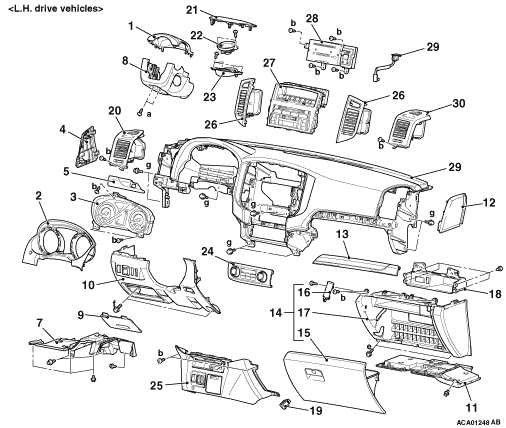
Do not insert the ornament remover in the area shown in the figure to prevent the deformation of instrument panel.

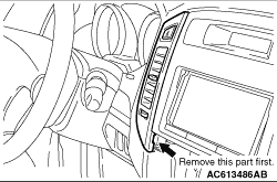
First remove the part shown in the figure when removing the centre air outlet.


<<B>> GLOVE BOX LOCK CYLINDER REMOVAL


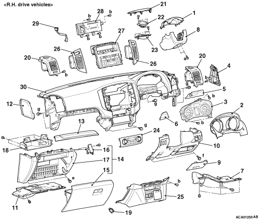
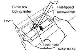
While pulling the lever as shown in the figure, press in the lock plate of the glove box lock cylinder (brass-coloured portion) using a flat-tipped screwdriver and push out the glove box lock cylinder to the direction of the arrow.
note Always unlock the glove box lock cylinder before removal because the glove box lock cylinder cannot be removed when it is locked.

INSTALLATION SERVICE POINT


>>A<< GLOVE BOX LOCK CYLINDER INSTALLATION


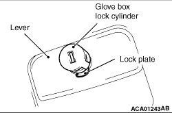
1.Set the glove box lock cylinder in the direction shown in the figure, and insert the lock plate to the installation hole of the lever.
2.Press in the glove box lock cylinder.

CLIP AND CLAW POSITIONS


note Each number in the illustration indicates a part number.