|
|
- Check whether users have experienced the lack of fuel or not.
|
|
|
Q.
Has the user ever experienced the lack of fuel?
|
|
|
 Erase the diagnosis codes to finish the check. Erase the diagnosis codes to finish the check.
|
|
|
|
|
|
- Refer to Data List Reference Table
 . .
- Item 02: Crank angle sensor
|
|
|
Q.
Is the check result normal?
|
|
|
 Check crank angle sensor system (Refer to Code No. P0335 ). Check crank angle sensor system (Refer to Code No. P0335 ).
|
|
|
|
|
|
- Refer to Data List Reference Table .
|
|
|
- Item 06: Engine coolant temperature sensor
- Item 26: Long-term fuel compensation 1
- Item 27: Long-term fuel compensation 2
- Item 28: Short-term fuel compensation 1
- Item 29: Short-term fuel compensation 2
|
|
|
Q.
Are the check results normal?
|
|
|
Perform the diagnosis code classified check procedure for the sensor that has
shown an abnormal data valve (Refer to Inspection Chart for Diagnosis Code ).
|
|
|
|
|
|
- Remove the spark plug and install it to the ignition
coil.
- Connect the ignition coil connector.
- Disconnect all injector connector.
- At the engine start, check each spark plug produces a spark.
|
|
|
Q.
Is the check result normal?
|
|
|
- Check spark plug itself (Refer to GROUP 16 - Ignition System <6G7> - On-vehicle
Service - Spark Plug Check and Cleaning ).
|
|
|
Q.
Is the check result normal?
|
|
|
Check ignition circuit system (Refer to Inspection Procedure 26 ).
|
|
|
|
|
|
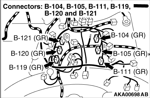
- B-119 (No. 1 injector connector)
- B-111 (No. 2 injector connector)
- B-120 (No. 3 injector connector)
- B-105 (No. 4 injector connector)
- B-121 (No. 5 injector connector)
- B-104 (No. 6 injector connector)
|
|
|
Q.
Are the check results normal?
|
|
|
Repair or replace the connector.
|
|
|
|
|
|
- Check injector itself (Refer to ).
|
|
|
Q.
Is the check result normal?
|
|
|
- Fuel pressure measurement (Refer to )
|
|
|
Q.
Is the check result normal?
|
|
|
Q.
Is the check result normal?
|
|
|
Q.
Is the check result normal?
|
|
|
- Check exhaust gas recirculation control solenoid valve itself (Refer to GROUP
17 - Emission Control <6G7> - Exhaust Gas Recirculation (EGR) Valve - EGR
Control Solenoid Valve Check <6G72> ).
|
|
|
Q.
Is the check result normal?
|
|
|
Replace the exhaust gas recirculation control solenoid valve.
|
|
|
|
|
|
- Check exhaust gas recirculation valve itself (Refer to GROUP 17 - Emission
Control <6G7> - Exhaust Gas Recirculation (EGR) Valve - EGR Valve Check <6G72> ).
|
|
|
Q.
Is the check result normal?
|
|
|
Replace the exhaust gas recirculation valve.
|
|
|
|
|
|
- Check compression pressure (Refer to GROUP 11E - On-vehicle Service - Compression
Pressure Check ).
|
|
|
Q.
Is the check result normal?
|
|
|
Repair the compression pressure.
|
|
|
|
|
|
Q.
Does trouble symptom persist?
|
|
|
Replace the engine-ECU <M/T> or engine-A/T-ECU <A/T>.
|
|
|
|
|
|
Intermittent malfunction (Refer to GROUP 00 - How to Use Troubleshooting/Inspection
Service Points - How to Cope with Intermittent Malfunctions ).
|
|
|
|