Code No. P0301: No. 1 Cylinder Misfire Detected

OPERATION
- Refer to Code No. P0201: No. 1 Injector System
 .
.
FUNCTION
- If a misfire occurs while the engine is running, the engine
speed changes for an instant.
- The engine-A/T-ECU checks for such changes in engine speed.
TROUBLE JUDGMENT
Check Conditions
- Engine speed is 440 -
4,500 r/min.
- Engine coolant temperature and intake air temperature are more than -10°C.
- Barometric pressure is less than 106 kPa.
- Volumetric efficiency is between 15 %
and 100 %.
- The learning compensation control that absorbs the difference in the target location
showing the crank position is completed.
- During the usual operation, the amount of throttle change is small: between -0.06
V/10 ms and +0.06 V/10 ms.
- Misfire has occurred more frequently than the limit during the last 200 revolutions
(when the catalyst temperature has been 950°C or higher).
or - When the engine often misfires within the last 1,000 revolutions from when the exhaust
gas exceeds the E-OBD regulation value.
PROBABLE CAUSES
- Ignition system related part(s) failed
- Low compression pressure
- Failed engine-A/T-ECU
DIAGNOSIS PROCEDURE |
STEP 1. Check ignition coil spark. |
Q.
Is the check result normal?
|
 Go to Step 2 . Go to Step 2 . |
|
 Check ignition circuit system (Refer to Inspection procedure 25 ) Check ignition circuit system (Refer to Inspection procedure 25 ) |
|
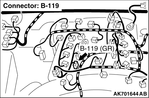
STEP 2. Connector check: B-119 No. 1 injector connector |
Q.
Is the check result normal?
|
| Go to Step 3 . |
|
| Repair or replace the connector. |
|
STEP 3. Check No. 1 injector itself. |
|
Q.
Is the check result normal?
|
| Go to Step 4 . |
|
| Replace the No. 1 injector. |
|
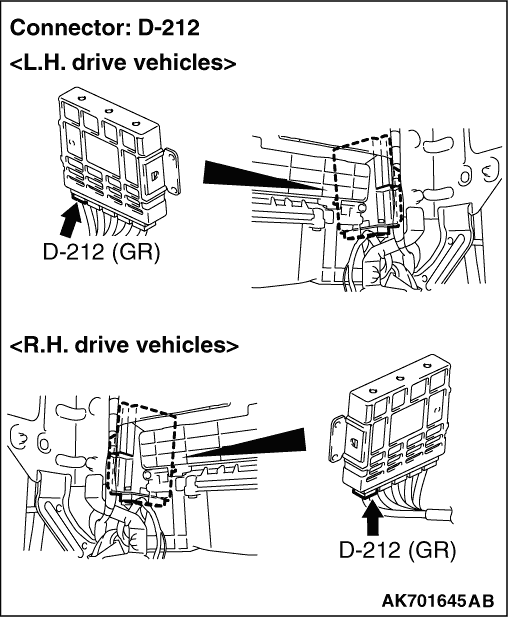
STEP 4. Connector check: B-15X engine control relay connector and B-212 engine-A/T-ECU connector |
Q.
Are the check results normal?
|
| Go to Step 5 . |
|
| Repair or replace the connector. |
|
STEP 5. Check harness between B-15X (terminal No. 1) engine control relay connector and B-119 (terminal No. 1) No. 1 injector connector. |
|
|
Q.
Is the check result normal?
|
| Go to Step 6 . |
|
| Repair the damaged harness wire. |
|
STEP 6. Check harness between B-119 (terminal No. 2) No. 1 injector connector and D-212 (terminal No. 1) engine-A/T-ECU connector |
|
|
Q.
Is the check result normal?
|
| Go to Step 7 . |
|
| Repair the damaged harness wire. |
|
STEP 7. Fuel pressure measurement. |
|
Q.
Is the check result normal?
|
| Go to Step 8 |
|
| Repair. |
|
STEP 8. M.U.T.-III diagnosis code |
|
Q.
Is the diagnosis code set?
|
| Replace the engine-A/T-ECU. |
|
| Intermittent malfunction (Refer to GROUP 00 -
How to Use Troubleshooting/Inspection
Service Points -
How to Cope with Intermittent Malfunctions ). |
|