REMOVAL AND INSTALLATION


caution
  • When the engine-ECU replacement is performed, always refer to GROUP 54A - Immobilizer System, On-vehicle Service, How to Register Key ID <3200> .
  • When the engine-ECU is replaced, register the injector identification code and perform the fuel injection learning (Refer to GROUP 00 - Precautions Before Service, What The Common Rail Engine Learns ).
  • After registering the injector identification code, perform the forcible DPF regeneration. (Refer to GROUP 17 - Diesel Particulate Filter (DPF) System, Forcible DPF Regeneration ).
  • If the battery current sensor or engine-ECU is replaced, make the battery current sensor learn the zero point. (Refer to GROUP 00, Precautions Before Service - Battery Current Sensor Calibration ).
Pre-removal Operation
  • Front Scuff Plate Outer and Cowl Side Trim Removal (Refer to GROUP 52A - Trim ) <Passenger’s Side>.

Post-installation Operation
  • Front Scuff Plate Outer and Cowl Side Trim Installation (Refer to GROUP 52A - Trim ) <Passenger’s Side>.


<L.H. drive vehicles>


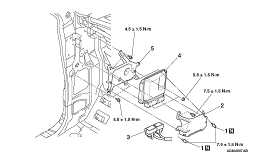
Removal steps

>>C<<
·
Initialisation operation (only at installation)


·
Passenger’s side lower cover and glove box assembly (Refer to GROUP 52A - Instrument Panel Assembly ).
<<A>>
>>A<<
1.
Engine-ECU connector connection
<<B>>

2.
Engine-ECU
<<C>>

3.
ECU bracket


<R.H. drive vehicles>


Removal steps

>>C<<
·
Initialisation operation (only at installation)


·
Instrument panel assembly (Refer to GROUP 52A - Instrument Panel Assembly ).
<<D>>
>>B<<
1.
Break off bolt


2.
Connector cover
<<A>>
>>A<<
3.
Engine-ECU connector connection


4.
Engine-ECU
<<C>>

5.
ECU bracket

REMOVAL SERVICE POINTS


<<A>> ENGINE-ECU CONNECTOR DISCONNECTION


caution Be sure to press the connector cover when turning the lock lever, or the connector may be damaged.
note If the connector cover should come off, engage the lock lever gear with the connector gear. Then, install the connector cover to the connector. Press the lock button to unlock the lock lever. While pressing the connector cover against the connector, turn the lock lever to the vertical position. Then, disconnect the connector from the engine-ECU.

Press the lock button to unlock the lock lever. While pressing the connector cover against the engine-ECU, turn the lock lever to the vertical position. Then, disconnect the connector from the engine-ECU.

<<B>> ENGINE-ECU REMOVAL <L.H. DRIVE VEHICLES>


1.Disconnect the wiring harness connectors installed to the front pillar to provide sufficient clearance for engine-ECU removal.
2.Remove the engine-ECU.

<<C>> ECU BRACKET REMOVAL


1.Disconnect the wiring harness connector(s) installed on the backside of the ECU bracket.
2.Remove the ECU bracket.

<<D>> BREAK OFF BOLT REMOVAL <R.H. DRIVE VEHICLES>


1.Drill in the break off bolt a hole deep enough for the tap to stand.
2.Use the recommended tool screw extractor set (MB992678) or equivalent to remove the break off bolt.

INSTALLATION SERVICE POINTS


>>A<< ENGINE-ECU CONNECTOR CONNECTION


1.
caution When inserting the connector to the engine-ECU, be careful not to apply force in the directions other than the inserting direction.
Move the lock lever of the connector to the unlock status, and then install the connector to the engine-ECU. Insert the connector as far as it goes.
2.
caution Make sure that the connector is inserted sufficiently before locking it, or the lock lever may be damaged.
While pressing the connector toward the engine-ECU side, turn the lock lever to lock the connector.

>>B<< BREAK OFF BOLT INSTALLATION <R.H. DRIVE VEHICLES>


Tighten the break off bolt until its head is broken off.

>>C<< INITIALISATION PROCEDURE


Turn the ignition switch on then off, and keep it off for at least 10 seconds.