|
|
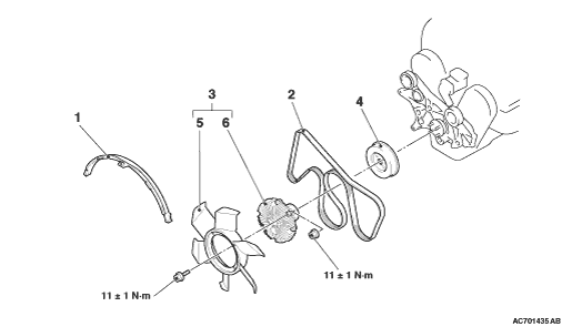
1.Before removing the drive belt, slightly loosen the mounting nuts of cooling fan clutch
and cooling fan pulley.
|
|
2.The following operations will be needed due to the introduction of the serpentine
drive system with the drive belt auto-tensioner.
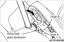
(1)
Securely insert the spindle handle or ratchet handle with a 12.7 mm insertion angle into
the jig hole of the drive belt auto-tensioner.
(2)
Rotate the drive belt auto-tensioner clockwise and align hole A with hole B.
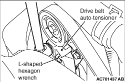
(3)
|
|
| caution |
To reuse the drive belt, draw an arrow indicating the
rotating direction (clockwise) on the back of the belt using chalk, etc.
|
|
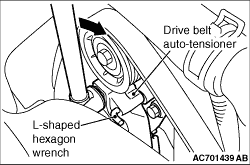
Insert an L-shaped hexagon wrench, etc. into the hole to fix and then remove the drive belt.
|
|
|
Temporarily tighten the mounting nuts of the cooling fan clutch and cooling fan pulley,
and install the drive belt. Then, tighten the mounting nuts to the specified torque.
|
|
|
Tightening torque: 11 ± 1 N·m
|
|
1.
| caution |
- To reuse the drive belt,
install it while aligning the arrow mark on the backside of belt marked at the removal with
the rotating direction.
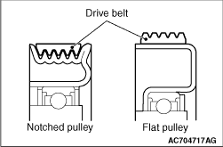
- Check if there is no deviation of the drive belt at the angle pulley.
- Check if the drive belt is installed onto the centre of the flat face of the flat pulley.
|
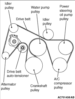
Install the drive belt to each pulley as shown in the figure.
|
|
2.Securely insert the spindle handle or ratchet handle with a 12.7 mm insertion angle into
the jig hole of the drive belt auto-tensioner.
3.Turn the alternator drive belt auto-tensioner clockwise slightly and remove the L-shaped
hexagon wrench that is used to fix the drive belt auto-tensioner.
4.Apply tension to the drive belt while slowly turning the spindle handle or ratchet
handle, which was rotating the drive belt auto-tensioner, anti-clockwise.
|