Code No.C1452: Front Propeller Shaft Speed Sensor System (Abnormal)


OPERATION
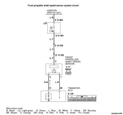
- The front propeller shaft speed sensor generates 0 <=> 5 V pulse signal when the front propeller shaft rotates. The pulse signal frequency increases with a rise in front propeller shaft speed.
- The front propeller shaft speed sensor is connected to the transfer-ECU (terminal No.12 and No.30) via the front propeller shaft speed sensor connector (terminal No.2 and No.1).
- The transfer-ECU detects the front propeller shaft speed by the signal input to terminal No.12.
- The front propeller shaft speed sensor generates the pulse signal as the hole in the front output shaft pass the magnetic tip of the sensor.
DIAGNOSIS CODE SET CONDITIONS
- In the case that the input signal from the front propeller shaft speed sensor is not input during the shift from 2WD to 4WD, the code No.C1452 is set.
- In the case that the input signal from the front propeller shaft speed sensor is unstable when the engage switch is ON condition, the code No.C1452 is set.
PROBABLE CAUSES
- Malfunction of the front propeller shaft speed sensor circuit
- Malfunction of the front output shaft
- Damaged harness wires and connectors
- Malfunction of the transfer-ECU
DIAGNOSIS PROCEDURE |
STEP 1. M.U.T.-III data list |
Item 12: Front propeller shaft speed sensor (Refer to data list reference table  ). ). |
Q.
Is the check result normal?
|
 Intermittent malfunction (Refer to GROUP 00 - How to Cope with Intermittent Malfunction ). Intermittent malfunction (Refer to GROUP 00 - How to Cope with Intermittent Malfunction ). |
|
 Go to Step 2. Go to Step 2. |
|
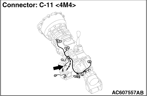
STEP 2. Measure the voltage at front propeller shaft speed sensor connector C-11. |
| (1)Disconnect the connector, and measure the voltage between terminal No.3 and earth at the wiring harness side. |
| (2)Turn the ignition switch to the ON position. OK: System voltage |
Q.
Is the check result normal?
|
| Go to Step 5. |
|
| Go to Step 3. |
|
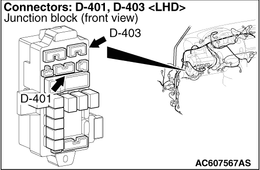
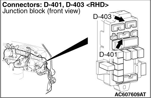
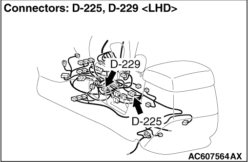
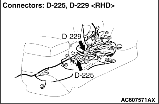
STEP 3. Connector check: D-401 J/B connector, D-225, D-229 intermediate connector. |
| Check for the contact with terminals. |
Q.
Is the check result normal?
|
| Go to Step 4. |
|
| Repair the defective connector. |
|
STEP 4. Check the harness between front propeller shaft speed sensor connector C-11 terminal No.3 and J/B connector D-401 terminal No.12. |
| Check the power supply line for short or open circuit. |
Q.
Is the check result normal?
|
| Go to Step 5. |
|
| Repair the wiring harness. |
|
STEP 5. Measure the voltage at front propeller shaft speed sensor connector C-11. |
| (1)Disconnect the connector, and measure the voltage between terminal No.2 and earth at the wiring harness side. |
| (2)Turn the ignition switch to the ON position. OK: 4.5 - 4.9 V |
Q.
Is the check result normal?
|
| Go to Step 11. |
|
| Go to Step 6. |
|
STEP 6. Measure the voltage at transfer-ECU connector D-124. |
| (1)Disconnect front propeller shaft speed sensor connector C-11. |
| (2)Measure the voltage between transfer-ECU connector D-124 terminal No.12 and earth at the ECU side. |
| (3)Turn the ignition switch to the ON position. OK: 4.5 - 4.9 V |
Q.
Is the check result normal?
|
| Go to Step 7. |
|
| Go to Step 9. |
|
STEP 7. Connector check: C-11 front propeller shaft speed sensor connector, D-124 transfer-ECU connector. |
| Check for the contact with terminals. |
Q.
Is the check result normal?
|
| Go to Step 8. |
|
| Repair the defective connector. |
|
STEP 8. Check the harness between front propeller shaft speed sensor connector C-11 terminal No.2 and transfer-ECU connector D-124 terminal No.12. |
| Check the output line for open circuit. |
Q.
Is the check result normal?
|
| Go to Step 19. |
|
| Repair the wiring harness. |
|
STEP 9. Connector check: C-11 front propeller shaft speed sensor connector, D-124 transfer-ECU connector. |
| Repair the defective connector. |
Q.
Is the check result normal?
|
| Go to Step 10. |
|
| Repair the defective connector. |
|
STEP 10. Check the harness between front propeller shaft speed sensor connector C-11 terminal No.2 and transfer-ECU connector D-124 terminal No.12. |
| Check the output line for short circuit. |
Q.
Is the check result normal?
|
| Go to Step 11. |
|
| Repair the wiring harness. |
|
STEP 11. Measure the resistance at front propeller shaft speed sensor connector C-11. |
| Disconnect the connector, and measure the resistance between terminal No.1 and earth at the wiring harness side. |
| OK: Continuity (2 Ω or less) |
Q.
Is the check result normal?
|
| Go to Step 16. |
|
| Go to Step 12. |
|
STEP 12. Measure the voltage at transfer-ECU connector D-124. |
| (1)Do not disconnect front propeller shaft speed sensor connector C-11. |
| (2)Measure the voltage between transfer-ECU connector D-124 terminal No.30 and earth at the ECU side. |
| (3)Turn the ignition switch to the ON position. OK: 5 V or less |
Q.
Is the check result normal?
|
| Go to Step 13. |
|
| Go to Step 15. |
|
STEP 13. Connector check: C-11 front propeller shaft speed sensor connector, D-124 transfer-ECU connector. |
| Check for the contact with terminals. |
Q.
Is the check result normal?
|
| Go to Step 14. |
|
| Repair the defective connector. |
|
STEP 14. Check the harness between front propeller shaft speed sensor connector C-11 terminal No.1 and transfer-ECU connector D-124 terminal No.30. |
| Check the earth line for open circuit. |
Q.
Is the check result normal?
|
| Go to Step 16. |
|
| Repair the wiring harness. |
|
STEP 15. Connector check: D-124 transfer-ECU connector. |
| Check for the contact with terminals. |
Q.
Is the check result normal?
|
| Replace the transfer-ECU. |
|
| Repair the defective connector. |
|
STEP 16. Measure the output wave pattern of the front propeller shaft speed sensor at transfer-ECU connector D-124 (using an oscilloscope). |
| (1)Transfer shift lever position: 4HLc. |
| (2)Start the engine and drive the vehicle at constant speed of 30 km/h. |
| (3)Connect an oscilloscope, and measure the voltage between transfer-ECU connector D-124 terminal No.12 and No.30. |
| (4)Check the front propeller shaft speed sensor waveform. OK: A wave pattern such as the one shown on (Inspection Procedure Using an Oscilloscope ) should be output, and the maximum value should be 4.8 V or more and the minimum value should be 0.6 V or less. There should be no noise in the output wave pattern. |
Q.
Is the check result normal?
|
| Go to Step 19. |
|
| Go to Step 17. |
|
STEP 17. Check the front propeller shaft speed sensor and then recheck the diagnosis code. |
| (1)Remove the front propeller shaft speed sensor. Wipe any metallic particles or dirt off the sensor tip. If the front propeller shaft speed sensor has damage, replace the sensor. |
| (2)Install the front propeller shaft speed sensor and road test the vehicle. |
| (3)Check if the diagnosis code is set. |
Q.
Is diagnosis code No.C1452 set?
|
| Go to Step 18. |
|
| The inspection is complete. |
|
STEP 18. Front output shaft check |
| Visually check the front output shaft for damage. |
Q.
Is the check result normal?
|
| Investigate noise source, and resolve it. |
|
| Replace the front output shaft. |
|
STEP 19. M.U.T.-III data list |
| Item 12: Front propeller shaft speed sensor (Refer to data list reference table ). |
Q.
Is the check result normal?
|
| Intermittent malfunction (Refer to GROUP 00 - How to Cope with Intermittent Malfunction ). |
|
| Replace the transfer-ECU. |
|