|
|
Check if the diagnosis code is set.
|
|
|
Q.
Is diagnosis code No.C1457 set?
|
|
|
 Refer to diagnosis code No.C1457: Free-wheel Engage Solenoid Valve System Refer to diagnosis code No.C1457: Free-wheel Engage Solenoid Valve System  . .
|
|
|
|
|
|
Item 77: Free-wheel engage switch (Refer to data list reference table ).
|
|
|
Q.
Is the check result normal?
|
|
|
Intermittent malfunction (Refer to GROUP 00 -
How to Cope with Intermittent Malfunction ).
|
|
|
|
|
|
(1)Remove the free-wheel engage switch.
|
|
|
(2)Do not disconnect connector B-114.
|
|
|
(3)Turn the ignition switch to the ON position.
|
|
|
(4)Item 77: Free-wheel engage switch.
|
|
|
(5)When the free-wheel engage switch is released (OFF).
OK: M.U.T.-III display should be "OFF"
When the free-wheel engage switch is pressed (ON).
OK: M.U.T.-III display should be "ON"
|
|
|
Q.
Is the check result normal?
|
|
|
Refer to GROUP 26 -
On-vehicle Service .
|
|
|
Q.
Is the check result normal?
|
|
|
Repair or replace the actuator assembly and free-wheel engage clutch (Refer to GROUP 26 -
Differential Carrier and Free-wheel Clutch ).
|
|
|
|
|
|
 Repair or replace the free-wheel engage solenoid valve and vacuum hoses (Refer to GROUP 26 -
Solenoid Valve and Vacuum Hose ). Repair or replace the free-wheel engage solenoid valve and vacuum hoses (Refer to GROUP 26 -
Solenoid Valve and Vacuum Hose ).
|
|
|
|
|
|
Refer to GROUP 26 -
Differential Carrier and Free-wheel Clutch .
|
|
|
Q.
Is the check result normal?
|
|
|
Replace the free-wheel engage switch (Refer to GROUP 26 -
Differential Carrier and Free-wheel Clutch ).
|
|
|
|
|
|
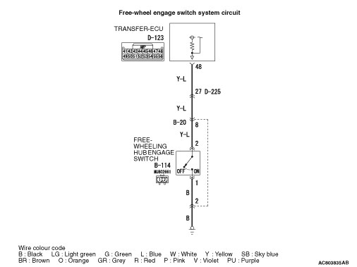
(1)Disconnect the connector, and measure the voltage between terminal No.2 and earth at the wiring harness side.
|
|
|
(2)Turn the ignition switch to the ON position.
OK: Approx. 10.5 V
|
|
|
Q.
Is the check result normal?
|
|
|
(1)Measure the voltage between terminal No.48 and earth at the ECU side.
|
|
|
(2)Transmission gear should be neutral position.
|
|
|
(3)Turn the ignition switch to the ON position.
OK:
- When the transfer shift lever position is 2H, voltage should measure approx. 10.5 V.
- When the transfer shift lever position is other than 2H, voltage should measure 1 V or less.
|
|
|
Q.
Is the check result normal?
|
|
|
Check for the contact with terminals.
|
|
|
Q.
Is the check result normal?
|
|
|
Repair the defective connector.
|
|
|
|
|
|
Check the output line for short circuit.
|
|
|
Q.
Is the check result normal?
|
|
|
Repair the wiring harness.
|
|
|
|
|
|
Check for the contact with terminals.
|
|
|
Q.
Is the check result normal?
|
|
|
Repair the defective connector.
|
|
|
|
|
|
Check the output line for open circuit.
|
|
|
Q.
Is the check result normal?
|
|
|
Repair the wiring harness.
|
|
|
|
|
|
Disconnect the connector, and measure the resistance between terminal No.1 and earth at the wiring harness side.
|
|
|
OK: Continuity (2 Ω
or less)
|
|
|
Q.
Is the check result normal?
|
|
|
Q.
Is the check result normal?
|
|
|
Repair the defective connector.
|
|
|
|
|
|
Check the earth line for open circuit.
|
|
|
Q.
Is the check result normal?
|
|
|
Repair the wiring harness.
|
|
|
|
|
|
Item 77: Free-wheel engage switch (Refer to data list reference table ).
|
|
|
Q.
Is the check result normal?
|
|
|
Intermittent malfunction (Refer to GROUP 00 -
How to Cope with Intermittent Malfunction ).
|
|
|
|
|
|
Replace the transfer-ECU.
|
|
|
|