|
|
- Item 25: Shift actuator current (Refer to
 ). ).
- Item 27: Shift actuator voltage (Refer to ).
|
|
|
Q.
Is the check result normal?
|
|
|
 Intermittent malfunction (Refer to GROUP 00 - How to Cope with Intermittent
Malfunction ). Intermittent malfunction (Refer to GROUP 00 - How to Cope with Intermittent
Malfunction ).
|
|
|
|
|
|
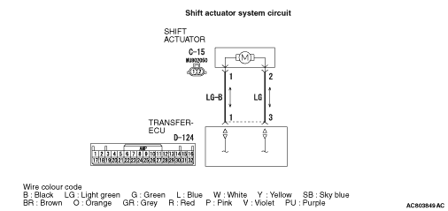
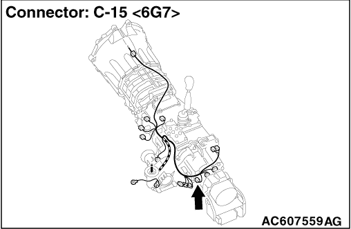
(1)Disconnect the shift actuator connector C-15.
|
|
|
(2)Turn the ignition switch to the ON position.
|
|
|
(3)Transmission gear should be neutral position.
|
|
|
(4)Measure the voltage between shift actuator connector C-15 terminal No.2 and earth
at the wiring harness side.
|
|
|
(5)When the operating transfer shift lever 2H → 4H, 4H → 4HLc or
4HLc → 4LLc.
OK: System voltage
|
|
|
(6)Measure the voltage between shift actuator connector C-15 terminal No.1 and earth
at the wiring harness side.
|
|
|
(7)When the operating transfer shift lever 4LLc → 4HLc, 4HLc → 4H
or 4H → 2H.
OK: System voltage
|
|
|
Q.
Is the check result normal?
|
|
|
Replace the shift actuator (Refer to GROUP 22B - Transfer ).
|
|
|
|
|
|
(1)Disconnect the shift actuator connector C-15.
|
|
|
(2)Turn the ignition switch to the ON position.
|
|
|
(3)Transmission gear should be neutral position.
|
|
|
(4)Measure the voltage between transfer-ECU connector D-124 terminal No.3 and earth
at the ECU side.
|
|
|
(5)When the operating transfer shift lever 2H → 4H, 4H → 4HLc or
4HLc → 4LLc.
OK: System voltage
|
|
|
(6)Measure the voltage between transfer-ECU connector D-124 terminal No.1 and earth
at the ECU side.
|
|
|
(7)When the operating transfer shift lever 4LLc → 4HLc, 4HLc → 4H
or 4H → 2H.
OK: System voltage
|
|
|
Q.
Is the check result normal?
|
|
|
Check for the contact with terminals.
|
|
|
Q.
Is the check result normal?
|
|
|
 Repair the defective connector. Repair the defective connector.
|
|
|
|
|
|
Check the output line for short circuit.
|
|
|
Q.
Is the check result normal?
|
|
|
Repair the wiring harness.
|
|
|
|
|
|
Check for the contact with terminals.
|
|
|
Q.
Is the check result normal?
|
|
|
Repair the defective connector.
|
|
|
|
|
|
Check the output line for open circuit.
|
|
|
Q.
Is the check result normal?
|
|
|
Repair the wiring harness.
|
|
|
|
|
|
- Item 25: Shift actuator current (Refer to ).
- Item 27: Shift actuator voltage (Refer to ).
|
|
|
Q.
Is the check result normal?
|
|
|
Intermittent malfunction (Refer to GROUP 00 - How to Cope with Intermittent
Malfunction ).
|
|
|
|
|
|
Replace the transfer-ECU.
|
|
|
|