
|
With the control finger at the neutral position, remove the spring pin.
|
|
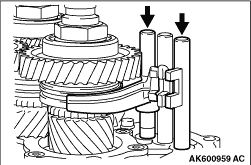
1.Slide the shift forks as illustrated to put the two gears into engagement.
|

|
2.Using the special tool, Lock nut wrench (46) (MD998835), remove the main shaft lock nut.
|

|
3.Using the special tool, Lock nut wrench (41) (MD998809), remove the counter shaft cluster
gear lock nut.
|
|
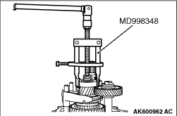
Using the special tool, Bearing and gear puller (MD998348), remove the ball bearing from
counter shaft cluster gear.
|
|
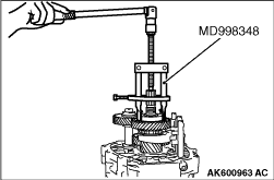
Using the special tool, Bearing and gear puller (MD998348), remove the ball bearing from
main shaft.
|

|
1.Attach the special tool, Bearing puller (MD998020), the reverse brake gear.
2.Screw the centre bolt of special tool, and pull out the reverse gear bearing sleeve,
reverse brake gear, synchronizer spring and ring together.
|

|
Lift the counter 5th speed gear to the slit in the reverse idler gear shaft and remove
them altogether.
|

|
While pushing the main shaft and counter shaft cluster gear against the intermediate plate,
remove the snap rings from the rear bearing retainer mounting surface.
|

|
Lightly tapping the intermediate plate with a plastic hammer or similar tool, remove the
intermediate plate from the main drive pinion, main shaft, and counter shaft cluster gear.
|

|
1.Install the main shaft and counter shaft cluster gear to the transmission case.
|

|
2.Using a plastic hammer, install the intermediate plate.
| note |
Push the intermediate plate until the snap ring grooves for the main shaft and counter
shaft cluster gear bearings come out the rear bearing retainer mounting surface.
|
3.Install the snap ring.
|

|
Apply the specified sealant to the threads.
Specified sealant: 3M™ STUD Locking No. 4170 or equivalent
| note |
The new bolt does not require sealant application as it is precoated with sealant.
|
|

|
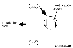
Press in the spring pin so that its slit is parallel with the shift rail.
|

|
1.Completely degrease the FIPG-applied surface so that water and oil including the old sealant
cannot adhere to the surface coated with the sealant.
Never touch the degreased surface by hand.
2.Apply the specified sealant to the transmission case before installation.
Specified sealant: Mitsubishi Part No. MD997740 or equivalent
|
|
|
Install the selected spacer into ball bearing. (Refer to ADJUSTMENT OF TRANSMISSION-SPACER
SELECTION FOR ADJUSTMENT OF BALL BEARING AXIAL PLAY  .) .)
|

|
1.Using special tool, Oil seal installer (MD998304), install the oil seal into the clutch
housing.
2.Apply specified grease to the lip of the oil seal.
Specified lubricant: Mitsubishi Part No. 0101011 or equivalent
|

|
1.Completely degrease the FIPG-applied surface so that water and oil including the old sealant
cannot adhere to the surface coated with the sealant.
Never touch the degreased surface by hand.
2.Apply the specified sealant to the transmission case before installation.
Specified sealant: Mitsubishi Part No. MD997740 or equivalent
|

|
Before reassembly, make sure that the counter 5th speed gear faces the correct direction.
|

|
Before reassembly, make sure that the 5th speed synchronizer hub faces the correct direction.
|

|
Using special tools to install the reverse brake gear.
- Installer cap (MD998812)
- Installer-100 (MD998813)
- Installer adapter (42) (MD998820)
|

|
Using special tools to install the reverse gear bearing sleeve.
- Installer cap (MD998812)
- Installer-100 (MD998813)
- Installer adapter (40) (MD998819)
|
|
Before reassembly, make sure that the 5th speed synchronizer sleeve faces the correct
direction.
|
|
Before reassembly, make sure that the reverse synchronizer sleeve faces the correct direction.
|

|
Install the poppet spring with the small end directed to the steel ball.
|

|
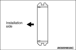
Press in the spring pin so that its slit is parallel with the shift rail.
|

|
Install the reverse gear while aligning the deep grooves in the synchronizer hub section
with the projection on the sleeve inner periphery.
|

|
Using special tools to install the ball bearing to the main shaft.
- Installer cap (MD998812)
- Installer-100 (MD998813)
- Installer adapter (40) (MD998819)
|

|
Before reassembly, make sure that the reverse idler gear faces the correct direction.
|

|
Before reassembly, make sure that the counter reverse gear faces the correct direction.
|

|
Using special tools to install the ball bearing to the counter shaft cluster gear.
- Installer cap (MD998812)
- Installer adapter (34) (MD998817)
|
|
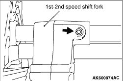
1.Slide the synchronizer sleeves as illustrated to put the two gears into engagement.
|

|
2.Using the special tool, Lock nut wrench (46) (MD998835), tighten the main shaft lock nut
to the specified torque of 255 ± 10 N·m.
|

|
3.Using the special tool, Lock nut wrench (41) (MD998809), tighten the counter shaft cluster
gear lock nut to the specified torque of 255 ± 10 N·m.
|

|
4.Stake the two lock nuts firmly using a punch or like.
|

|
1.Completely degrease the FIPG-applied surface so that water and oil including the old sealant
cannot adhere to the surface coated with the sealant.
Never touch the degreased surface by hand.
2.Apply specified sealant to the transmission case mating surface of the transfer case
adapter as illustrated.
Specified sealant: Mitsubishi Part No. MD997740 or equivalent
|

|
1.Apply the specified sealant to the bolt as shown.
Specified sealant: Mitsubishi Part No. MD997740 or equivalent
|

|
2.Apply the specified sealant to the nut threads.
Specified sealant: 3M ™ AAD Part No. 2353 or equivalent
|

|
Coat the entire surface of the neutral return plunger with grease. Then, install the neutral
return plunger to the upper cover and attach the spring.
Specified lubricant: Mitsubishi Part No. 0101011 or equivalent
|

|
1.Completely degrease the FIPG-applied surface so that water and oil including the old sealant
cannot adhere to the surface coated with the sealant.
Never touch the degreased surface by hand.
2.Apply a bead of specified sealant to the upper cover as illustrated.
Specified sealant: Mitsubishi Part No. MD997740 or equivalent
|

|
Apply the specified sealant to the resistance spring plug as illustrated.
Specified sealant: 3M ™ AAD Part No. 8660 or equivalent
|

|
Install the switches, ensuring that each is installed correctly as identified by the identification
tape.
|
|
Mounting position
|
Rail switch
|
Identification tape colour
|
A
|
1st and 2nd
|
Red
|
B
|
5th and reverse
|
White
|
|
|

|
1.Completely degrease the FIPG-applied surface so that water and oil including the old sealant
cannot adhere to the surface coated with the sealant.
Never touch the degreased surface by hand.
2.Apply specified sealant to the transfer case adapter mating surface of the transfer.
Specified sealant: Mitsubishi Part No. MD997740 or equivalent
|

|
3.Apply grease to the leading end of the transfer input gear as illustrated.
Specified lubricant: Mitsubishi Part No. 0101011 or equivalent
4.Assemble the transfer and transmission with care not to damage the control shaft oil
seal. At this time, mount the change shifter to the control shaft.
|

|
1.Completely degrease the FIPG-applied surface so that water and oil including the old sealant
cannot adhere to the surface coated with the sealant.
Never touch the degreased surface by hand.
2.Apply specified sealant to the illustrated position of the control housing.
Specified sealant: Mitsubishi Part No. MD997740 or equivalent
|

|
Install the switches as illustrated.
|
|
Mounting Position
|
Switch Name
|
Tube colour
|
Connector colour
|
A
|
2WD/4WD detection switch
|
Blue
|
Black
|
B
|
4LLC operation detection switch
|
Black
|
Brown
|
C
|
2WD detection switch
|
Black
|
Black
|
D
|
4H detection switch
|
Green
|
White
|
E
|
Centre differential lock detection switch
|
Blue
|
Brown
|
|
|


