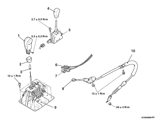
REMOVAL AND INSTALLATION


Pre-removal OperationMove the selector lever to the following positions.

  • Selector lever: N
Post-installation Operation
  • Transmission Control Cable Adjustment (Refer to ).
  • Check that the selector lever and the transfer control lever are moved to each position smoothly and correctly.


Selector lever assembly removal steps


1.
Selector knob


2.
Knob cover


3.
Sleeve


4.
Transfer shift lever knob


·
Shift indicator panel (Refer to GROUP 52A - Floor Consol Assembly ).


5.
Transfer shift lever switch


6.
Key interlock cable connection (selector lever assembly side)


7.
Shift lock cable unit connection (selector lever assembly side)

>>A<<
8.
Transmission control cable connection


9.
Selector lever assembly


10.
Transmission control cable assembly

INSTALLATION SERVICE POINT


>>A<< KEY INTERLOCK CABLE (SELECTOR LEVER ASSEMBLY SIDE) INSTALLATION


1.Selector lever to P position.
2.Turn the ignition key to LOCK (OFF) position.

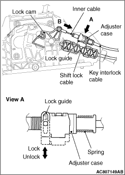
3.Install the tip of the key interlock cable to the lock cam of the selector lever assembly taking care not to twist the inner cable.
4.Lift the lock guide (unlocked position) and then install the adjuster case.
5.Lower the lock guide thoroughly and lock it.
note The lock position of the key interlock cable is automatically adjusted by a spring.