|
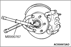
Use special tool front hub and flange yoke holder (MB990767) to fix the hub and remove
the axle nut.
|
|
|
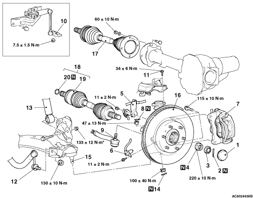
1.Remove the front caliper assembly with the brake hose.
|
|
|
2.Secure the removed front caliper assembly with a wire or other similar material at
a position where it will not interfere with the removal and installation of the brake disc, hub
and knuckle assembly.
|

|
1.Install special tool ball joint remover (MB991897 or MB992011) as shown in the figure.
|

|
2.Turn the bolt and knob as necessary to make the jaws of special tool parallel, tighten
the bolt by hand and confirm that the jaws are still parallel.
| note |
When adjusting the jaws in parallel, make sure the knob is in the position shown in the figure.
|
3.Tighten the bolt with a wrench to disconnect the tie rod end.
4.If the tie rod end ball joint is disengaged from the knuckle, always renew the tie
rod end ball joint dust cover and retainer.(Refer to GROUP 37-Power steering gear box and linkage  ) )
5.If the lower arm ball joint dust cover is damaged accidentally during service work,
replace the lower arm ball joint dust cover and retainer.(Refer to GROUP 33-Lower arm assembly )
|
|
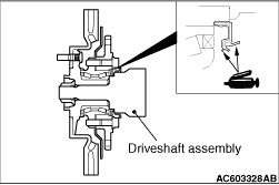
Apply multipurpose grease as shown in the illustration before install the driveshaft assembly.
|
|
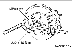
Using special tool front hub and flange yoke holder (MB990767), tighten the axle nut.
At this time, tighten the axle nut to the specified torque in expectation of final tightening.
|
|
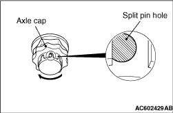
1.If axle cap is as shown after it is fitted, turn it at least one notch clockwise to align
it with the split pin hole.
|
|
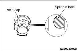
2.If the axle cap is as shown, turn it at least one notch anti-clockwise to align it with
the split pin hole.
3.If the split pin hole is not visible, turn it at least three notches clockwise to
align it with the split pin hole.
|