REMOVAL AND INSTALLATION


caution Do not apply grease or lubricant to the switch and the switch installation section to avoid malfunction of the switch. In addition, do not use gloves which have grease on them.
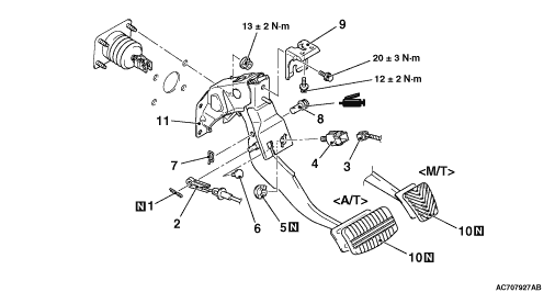
Post-installation OperationBrake Pedal Adjustment (Refer to ).


Removal steps


·
Instrument panel lower panel (Refer to GROUP 52A- Instrument Panel Assembly .)


1.
Split pin <A/T>


2.
Shift lock cable connection <A/T>


3.
Stop lamp switch connector connection


4.
Stop lamp switch


5.
Adjuster


6.
Pedal stopper


7.
Snap pin


8.
Pin assembly


9.
Guide bracket


10.
Pedal pad

>>A<<
11.
Brake pedal and pedal support member

INSTALLATION SERVICE POINT


>>A<< BRAKE PEDAL AND PEDAL SUPPORT MEMBER INSTALLATION


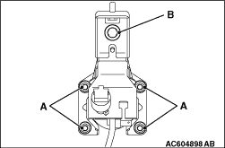
Tighten the brake booster mounting nuts (A), and then the brake pedal mounting bolts (B).
note The pedal support member cannot be positioned correctly if the pedal mounting bolts (B) are tightened first as their holes are oblong holes.