Code No.21: Wheel
Speed Sensor (FR) System
Code No.22: Wheel Speed Sensor (FL) System
Code No.23:
Wheel Speed Sensor (RR) System
Code No.24: Wheel Speed Sensor (RL) System
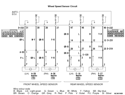
<LHD>
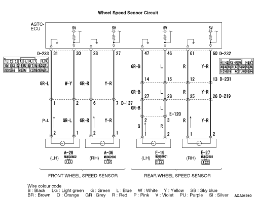
<RHD>
|
|
| caution |
If there is any problem in
the CAN bus lines, an incorrect diagnosis code may be set. Diagnose the CAN bus lines before
the diagnosis codes (Refer to GROUP 54D, CAN bus-line diagnostic flow  ). ).
|
|
|
|
- A toothed rotor generates a voltage signal as it moves across the pickup
field of each wheel speed sensor.
- The amount of voltage generated at each wheel is determined by the clearance between
the rotor teeth and the wheel speed sensor, and by the speed of rotation.
- The wheel speed sensors transmit the frequency of the voltage signal to the Active
stability and traction control system-electronic control unit (ASTC-ECU).
- The ABS hydraulic unit modulates the amount of braking force individually applied
to each wheel cylinder.
|
|
|
DIAGNOSIS CODE SET CONDITIONS
|
|
|
Diagnosis codes No. 21, 22, 23, and 24 are set in the following cases.
|
|
|
- Although no open circuit is found, no input signal from the wheel speed sensors
of one or more wheels is received.
- Any abnormality is found with the input signals from the wheel speed sensors.
|
|
|
The most likely causes for these diagnosis codes to set are:
|
|
|
- Malfunction of the wheel speed sensor
- Damaged wiring harness or connector
- Malfunction of the rotor
- The gap between the wheel speed sensor and the rotor is excessive.
- Wheel bearing malfunction
- Malfunction of the ASTC-ECU
|
|
|
STEP 1. M.U.T.-III CAN bus diagnostics
|
|
|
| caution |
Before connecting or disconnecting the M.U.T.-III, turn the ignition
switch to the "LOCK" (OFF) position.
|
|
|
|
(1)Connect M.U.T.-III to the 16-pin diagnosis connector.
|
|
|
(2)Turn the ignition switch to the "ON" position.
|
|
|
(3)Diagnose the CAN bus line.
|
|
|
(4)Turn the ignition switch to the "LOCK" (OFF) position.
|
|
|
Q.
Is the check result normal?
|
|
|
 Go to Step 3. Go to Step 3.
|
|
|
|
|
|
 Repair the CAN bus line (Refer to GROUP 54D, CAN bus line Diagnostic flow ).
Then go to Step 2. Repair the CAN bus line (Refer to GROUP 54D, CAN bus line Diagnostic flow ).
Then go to Step 2.
|
|
|
|
|
|
STEP 2. Check whether the diagnosis code is reset.
|
|
|
| caution |
Before connecting or disconnecting the M.U.T.-III, turn the ignition
switch to the "LOCK" (OFF) position.
|
|
|
|
(1)Turn the ignition switch to the "ON" position.
|
|
|
(2)Erase the diagnosis code.
|
|
|
(3)Turn the ignition switch to the "LOCK" (OFF) position.
|
|
|
(4)Turn the ignition switch to the "ON" position.
|
|
|
(5)Disconnect the M.U.T.-III.
|
|
|
(6)Drive the vehicle with speed exceeds 15 km/h to recognize wheel signals to the
ASTC-ECU.
|
|
|
(7)Check if the diagnosis code is set.
|
|
|
(8)Turn the ignition switch to the "LOCK" (OFF) position.
|
|
|
Q.
Is code No.21, 22, 23 or 24 set?
|
|
|
Go to Step 3.
|
|
|
|
|
|
The procedure is complete.
|
|
|
|
|
|
STEP 3. Check the installation condition of the wheel speed sensors.
|
|
|
Check whether the front right wheel speed sensor or its mounting bolts are loosened.
|
|
|
Q.
Is the check result normal?
|
|
|
Go to Step 4.
|
|
|
|
|
|
Reinstall the wheel speed sensor correctly. Then go to Step 13.
|
|
|
|
|
|
STEP 4. Inspect the wheel speed sensor.
|
|
|
Check the wheel speed sensor relevant to the diagnosis code. For the applicable inspection
procedure, refer to .
|
|
|
- When code No.21 is set: Front right wheel speed sensor
- When code No.22 is set: Front left wheel speed sensor
- When code No.23 is set: Rear right wheel speed sensor
- When code No.24 is set: Rear left wheel speed sensor
|
|
|
Q.
Is the check result normal?
|
|
|
Go to Step 5.
|
|
|
|
|
|
NO <Front right wheel speed sensor>  : Go to Step 7. : Go to Step 7.
|
|
|
|
|
|
NO <Front left wheel speed sensor> : Go to Step 8.
|
|
|
|
|
|
NO <Rear right wheel speed sensor> : Go to Step 9.
|
|
|
|
|
|
NO <Rear left wheel speed sensor> : Go to Step 10.
|
|
|
|
|
|
STEP 5. Check the wheel bearing for looseness.
|
|
|
| note |
If the wheel bearing is loose, the gap between the wheel speed sensor and rotor may become
excessive. Check the hub assembly, for looseness.
|
|
|
|
- When code No.21 is set: Check the front hub assembly <Refer to GROUP
26, Hub and knuckle assembly inspection (RH) >.
- When code No.22 is set: Check the front hub assembly <Refer to GROUP 26, Hub
and knuckle assembly inspection (LH) >.
- When code No.23 is set: Check the rear hub assembly <Refer to GROUP 27, Rear
axle hub assembly inspection (RH) >.
- When code No.24 is set: Check the rear hub assembly <Refer to GROUP 27, Rear
axle hub assembly inspection (LH) >.
|
|
|
Q.
Is the check result normal?
|
|
|
Go to Step 6.
|
|
|
|
|
|
NO (front wheel bearing backlash is not within the standard value) : Replace the front hub assembly (Refer to GROUP 26, Hub and knuckle assembly disassembly
and reassembly ). Then go to Step 13.
|
|
|
|
|
|
NO (rear wheel bearing backlash is not within the standard value) : Replace the rear hub assembly (Refer to GROUP 27, knuckle removal and installation ). Then
go to Step 13.
|
|
|
|
|
|
Check the rotor, for foreign material or deformation.
|
|
|
- When code No.21 is set: Check the front rotor <RH> (Refer to ).
- When code No.22 is set: Check the front rotor <LH> (Refer to ).
- When code No.23 is set: Check the rear rotor <RH> (Refer to ).
- When code No.24 is set: Check the rear rotor <LH> (Refer to ).
|
|
|
Q.
Is the check result normal?
|
|
|
Go to Step 11.
|
|
|
|
|
|
NO (front) : If the rotor is contaminated with foreign material, clean it. If the front hub
assembly is deformed, replace it (Refer to GROUP 26, Driveshaft assembly ).
Then go to Step 13.
|
|
|
|
|
|
NO (rear) : If the rotor is contaminated with foreign material, clean it. If the rear hub
assembly is deformed, replace it (Refer to GROUP 27, Driveshaft assembly ).
Then go to Step 13.
|
|
|
|
|
|
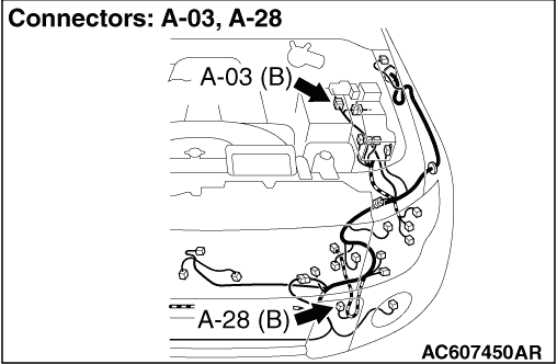
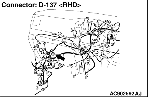
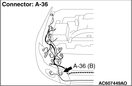
STEP 7. Check D-233 ASTC-ECU connector, A-03 intermediate connector <LHD>
or D-137 intermediate connector <RHD> and A-36 wheel speed sensor front: RH connector for
loose, corroded or damaged terminals, or terminals pushed back in the connector.
|
|
|
Q.
Is the check result normal?
|
|
|
Go to Step 11.
|
|
|
|
|
|
Repair or replace the damaged component(s). Then go to Step 13.
|
|
|
|
|
|
STEP 8. Check D-233 ASTC-ECU connector, A-03 intermediate connector <LHD>
or D-137 intermediate connector <RHD> and A-28 wheel speed sensor front: LH connector for
loose, corroded or damaged terminals, or terminals pushed back in the connector.
|
|
|
Q.
Is the check result normal?
|
|
|
Go to Step 11.
|
|
|
|
|
|
Repair or replace the damaged component(s). Then go to Step 13.
|
|
|
|
|
|
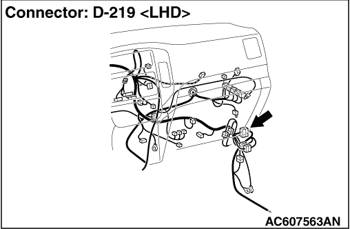
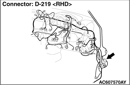
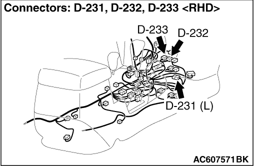
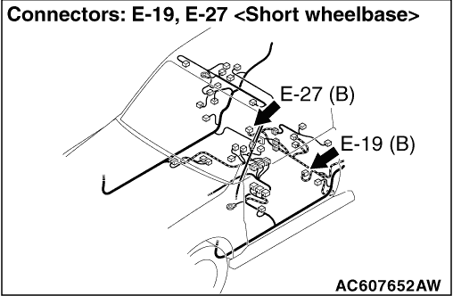
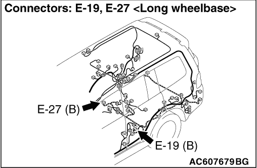
STEP 9. Check D-232 ASTC-ECU connector, D-219, D-231 intermediate
connector and E-19 wheel speed sensor rear: RH connector for loose, corroded or damaged terminals, or
terminals pushed back in the connector.
|
|
|
Q.
Is the check result normal?
|
|
|
Go to Step 11.
|
|
|
|
|
|
Repair or replace the damaged component(s). Then go to Step 13.
|
|
|
|
|
|
STEP 10. Check D-232 ASTC-ECU connector, D-219, D-231 intermediate
connector and E-19 wheel speed sensor rear: LH connector for loose, corroded or damaged terminals,
or terminals pushed back in the connector.
|
|
|
Q.
Is the check result normal?
|
|
|
Go to Step 11.
|
|
|
|
|
|
Repair or replace the damaged component(s). Then go to Step 13.
|
|
|
|
|
|
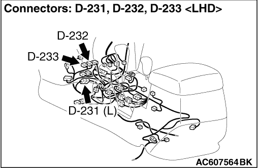
STEP 11. Resistance measurement at D-232, D-233 ASTC-ECU connector.
|
|
|
(1)Disconnect the D-232, D-233 ASTC-ECU connector.
|
|
|
(2)Measure the resistance between the ASTC-ECU connector terminals.
- Code No.21 is set: Between the D-233 ASTC-ECU connector terminal 27 and 28
- Code No.22 is set: Between the D-233 ASTC-ECU connector terminal 30 and 31
- Code No.23 is set: Between the D-232 ASTC-ECU connector terminal 60 and 61
- Code No.24 is set: Between the D-232 ASTC-ECU connector terminal 46 and 47
Standard Value: 1.0 - 1.5 kΩ
|
|
|
Q.
Is the check result normal?
|
|
|
Go to Step 12.
|
|
|
|
|
|
Replace the wheel speed sensor.Then go to Step 13.
|
|
|
|
|
|
STEP 12. Check whether the diagnosis code is reset.
|
|
|
Check again if the diagnosis code is set.
|
|
|
(1)Turn the ignition switch to the "ON" position.
|
|
|
(2)Erase the diagnosis code.
|
|
|
(3)Turn the ignition switch to the "LOCK" (OFF) position.
|
|
|
(4)Turn the ignition switch to the "ON" position.
|
|
|
(5)Disconnect the M.U.T.-III.
|
|
|
(6)Drive the vehicle with speed exceeds 15 km/h to recognize wheel signals to the
ASTC-ECU.
|
|
|
(7)Check if the diagnosis code is reset.
|
|
|
(8)Turn the ignition switch to the "LOCK" (OFF) position.
|
|
|
Q.
Is code No.21, 22, 23 or 24 set?
|
|
|
Replace the ASTC-ECU. Then go to Step 13.
|
|
|
|
|
|
It can be assumed that this malfunction is intermittent. Refer to GROUP 00, How
to Use Troubleshooting/Inspection Service Points - How to Cope with Intermittent
Malfunction .
|
|
|
|
|
|
STEP 13. Check whether the diagnosis code is reset.
|
|
|
(1)Turn the ignition switch to the "ON" position.
|
|
|
(2)Erase the diagnosis code.
|
|
|
(3)Turn the ignition switch to the "LOCK" (OFF) position.
|
|
|
(4)Turn the ignition switch to the "ON" position.
|
|
|
(5)Disconnect the M.U.T.-III.
|
|
|
(6)Drive the vehicle with speed exceeds 15 km/h to recognize wheel signals to the
ASTC-ECU.
|
|
|
(7)Check if the diagnosis code is set.
|
|
|
(8)Turn the ignition switch to the "LOCK" (OFF) position.
|
|
|
Q.
Is code No.21, 22, 23 or 24 set?
|
|
|
Repeat the troubleshooting from Step 1.
|
|
|
|
|
|
The procedure is complete.
|
|
|
|