Code No.86: Rear
Differential Lock Detection Switch Circuit Incomplete <Vehicles with Rear Differential
Lock>
|
|
| caution |
If there is any problem in the
CAN bus lines, an incorrect diagnosis code may be set. Diagnose the CAN bus lines before the
diagnosis codes (Refer to GROUP 54D, CAN bus-line diagnostic flow  ). ).
|
|
|
|
ASTC-ECU detects the rear differential lock operation status by the following information.
|
|
|
- Rear differential lock detection switch: ON
- Rear differential lock indicator signal: illuminates or flashes
|
|
|
If one or more of these signals become effective, it is judged that the rear differential
lock is activated and ABS (EBD)/ASC/TCL control is prohibited. The ASC indicator
lamp, the ASC OFF indicator lamp, the ABS warning lamp, and brake warning lamp illuminate at
the same time.
|
|
|
DIAGNOSIS CODE SET CONDITIONS
|
|
|
The code is set when "the rear differential lock engage switch: ON" as well as "the rear
differential lock indicator signal: OFF" are received simultaneously for a specified period.
|
|
|
- Damaged wiring harness or connector
- Malfunction of rear differential lock detection switch
- Malfunction of ASTC-ECU
|
|
|
STEP 1. M.U.T.-III CAN bus diagnostics
|
|
|
| caution |
Before connecting or disconnecting the M.U.T.-III, turn the
ignition switch to the "LOCK" (OFF) position.
|
|
|
|
(1)Connect M.U.T.-III to the 16-pin diagnosis connector.
|
|
|
(2)Turn the ignition switch to the "ON" position.
|
|
|
(3)Diagnose the CAN bus line.
|
|
|
(4)Turn the ignition switch to the "LOCK" (OFF) position.
|
|
|
Q.
Is the check result normal?
|
|
|
 Go to Step 3 Go to Step 3
|
|
|
|
|
|
 Repair the CAN bus line (Refer to GROUP 54D, CAN bus line Diagnostic flow ).
Then go to Step 2. Repair the CAN bus line (Refer to GROUP 54D, CAN bus line Diagnostic flow ).
Then go to Step 2.
|
|
|
|
|
|
STEP 2. Check whether the diagnosis code is reset.
|
|
|
(1)Turn the ignition switch to the "ON" position.
|
|
|
(2)Erase the diagnosis code.
|
|
|
(3)Turn the ignition switch to the "LOCK" (OFF) position.
|
|
|
(4)Turn the ignition switch to the "ON" position.
|
|
|
(6)Drive the vehicle more than 10 seconds at the speed exceeds 10 km/h.
|
|
|
(7)Check if the diagnosis code is set.
|
|
|
Go to Step 3
|
|
|
|
|
|
The procedure is complete.
|
|
|
|
|
|
STEP 3. Check the M.U.T.-III data list.
|
|
|
(1)Turn the ignition switch to the "ON" position.
|
|
|
(2)Operate the rear differential lock switch, and check if the operation status matches
the service data output.
- Item No.85: Rear differential lock
OK:
(Rear differential lock deactivated): LOCK
(Rear differential lock activated, being switched): UNLOCK
- Item No.86: Rear differential lock engage switch
OK:
(Rear differential lock engage switch: ON): ON
(Rear differential lock engage switch: OFF): OFF
- Item No.87: Rear differential lock indicator
OK:
(Rear differential lock indicator: ON): ON
(Rear differential lock indicator: OFF): OFF
|
|
|
Q.
Is the check result normal?
|
|
|
Go to Step 16
|
|
|
|
|
|
NO (Output of item No. 85 or No. 86 is unmatched) : Go to Step 4 : Go to Step 4
|
|
|
|
|
|
NO (Item No. 87 output unmatched) : Go to Step 13
|
|
|
|
|
|
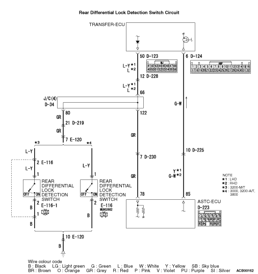
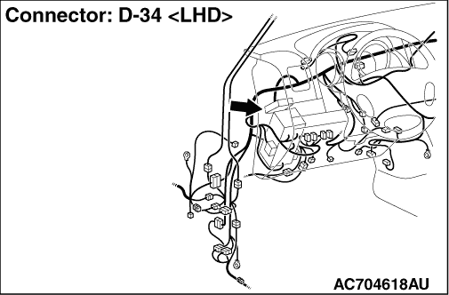
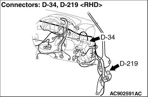
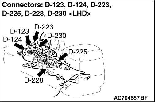
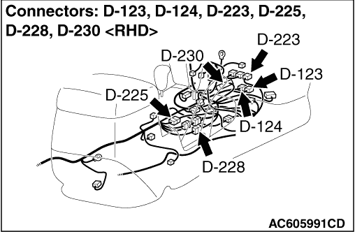
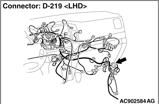
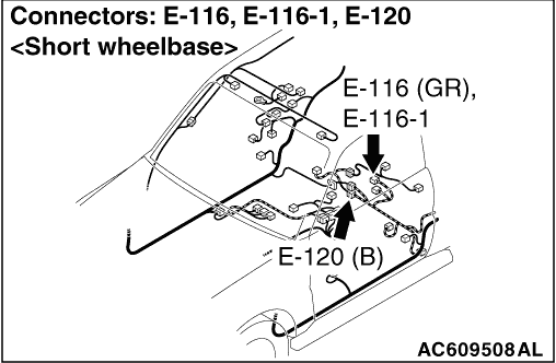
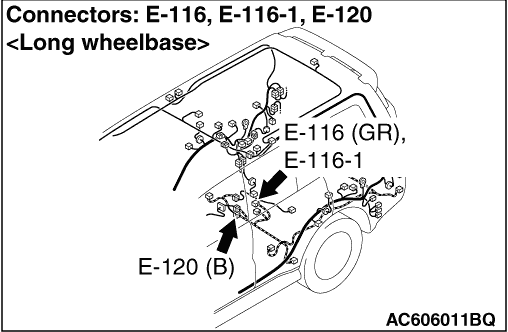
STEP 4. Connector check: D-223 ASTC-ECU connector, D-34 joint connector,
D-123 transfer-ECU connector, D-219 intermediate connector, D-228 intermediate connector, D-230
intermediate connector, E-116 intermediate connector <3200-M/T>,
E-116 rear differential lock detection switch connector <3000, 3200-A/T, 3800>,
E-120 intermediate connector and E-116-1 rear differential lock detection switch connector <3200-M/T>.
|
|
|
Q.
Is the check result normal?
|
|
|
Go to Step 5
|
|
|
|
|
|
Repair or replace the damaged component(s). Then go to Step 18.
|
|
|
|
|
|
STEP 5. Resistance measurement at the D-34 joint connector and E-116-1
rear differential lock detection switch connector <3200-M/T> or E-116
rear differential lock detection switch connector <3000, 3200-A/T, 3800>
|
|
|
(1)Disconnect the D-34 joint connector and E-116-1 rear differential lock detection
switch connector <3200-M/T> or E-116 rear differential lock detection
switch connector <3000, 3200-A/T, 3800> and measure the resistance
at the harness side.
|
|
|
(2)Measure the resistance between the D-34 joint connector terminal No.80 and E-116-1
rear differential lock detection switch connector <3200-M/T> terminal
No.1 or E-116 rear differential lock detection switch connector <3000, 3200-A/T, 3800> terminal
No.1.
OK: Continuity exists (2 Ω or less)
|
|
|
Q.
Is the check result normal?
|
|
|
Go to Step 6
|
|
|
|
|
|
Repair the wiring harness. Then go to Step 18.
|
|
|
|
|
|
STEP 6. Resistance measurement at the D-34 joint connector
|
|
|
(1)Disconnect the D-34 joint connector and E-116-1 rear differential lock detection
switch connector <3200-M/T> or E-116 rear differential lock detection
switch connector <3000, 3200-A/T, 3800> and measure the resistance at the
harness side.
|
|
|
(2)Measure the resistance between the D-34 joint connector terminal No.80 and body
earth.
OK: No continuity
|
|
|
Q.
Is the check result normal?
|
|
|
Go to Step 7
|
|
|
|
|
|
Repair the wiring harness. Then go to Step 18.
|
|
|
|
|
|
STEP 7. Resistance measurement at the E-116-1 rear differential lock
detection switch connector <3200-M/T> or E-116 rear differential
lock detection switch connector <3000, 3200-A/T, 3800> and body earth
|
|
|
(1)Disconnect the E-116-1 rear differential lock detection switch connector <3200-M/T> or
E-116 rear differential lock detection switch connector <3000, 3200-A/T, 3800> and
measure the resistance at the harness side.
|
|
|
(2)Measure the resistance between the E-116-1 rear differential lock detection switch
connector <3200-M/T> terminal No.2 or E-116 rear differential lock
detection switch connector <3000, 3200-A/T, 3800> terminal No.2 and body earth.
OK: Continuity exists (2 Ω or less)
|
|
|
Q.
Is the check result normal?
|
|
|
Go to Step 8
|
|
|
|
|
|
Repair the wiring harness. Then go to Step 18.
|
|
|
|
|
|
STEP 8. Check the rear differential lock detection switch.
|
|
|
Refer to GROUP 27 - Rear Differential Lock Detection Switch Check .
|
|
|
Q.
Is the check result normal?
|
|
|
Go to Step 9
|
|
|
|
|
|
Replace it. Then go to Step 18.
|
|
|
|
|
|
STEP 9. Resistance measurement at the D-34 joint connector and D-123
transfer-ECU connector
|
|
|
(1)Disconnect the D-34 joint connector and D-123 transfer-ECU connector, and measure
the resistance at the harness side.
|
|
|
(2)Measure the resistance between the D-34 joint connector terminal No.66 and D-123
transfer-ECU connector terminal No.50.
OK: Continuity exists (2 Ω or less)
|
|
|
Q.
Is the check result normal?
|
|
|
Go to Step 10
|
|
|
|
|
|
Repair the wiring harness. Then go to Step 18.
|
|
|
|
|
|
STEP 10. Resistance measurement at the D-34 joint connector
|
|
|
(1)Disconnect the D-34 joint connector and D-123 transfer-ECU connector, and measure
the resistance at the harness side.
|
|
|
(2)Measure the resistance between the D-34 joint connector terminal No.66 and body
earth.
OK: No continuity
|
|
|
Q.
Is the check result normal?
|
|
|
Go to Step 11
|
|
|
|
|
|
Repair the wiring harness. Then go to Step 18.
|
|
|
|
|
|
STEP 11. Resistance measurement at the D-34 joint connector and D-223
ASTC-ECU connector
|
|
|
(1)Disconnect the D-34 joint connector and D-223 ASTC-ECU connector, and measure the
resistance at the harness side.
|
|
|
(2)Measure the resistance between the D-34 joint connector terminal No.122 and D-223
ASTC-ECU connector terminal No.78.
OK: Continuity exists (2 Ω or less)
|
|
|
Q.
Is the check result normal?
|
|
|
Go to Step 12
|
|
|
|
|
|
Repair the wiring harness. Then go to Step 18.
|
|
|
|
|
|
STEP 12. Resistance measurement at the D-34 joint connector
|
|
|
(1)Disconnect the D-34 joint connector and D-223 ASTC-ECU connector, and measure the
resistance at the harness side.
|
|
|
(2)Measure the resistance between the D-34 joint connector terminal No.122 and body
earth.
OK: No continuity
|
|
|
Q.
Is the check result normal?
|
|
|
Go to Step 13
|
|
|
|
|
|
Repair the wiring harness. Then go to Step 18.
|
|
|
|
|
|
STEP 13. Connector check: D-223 ASTC-ECU connector, D-124 transfer-ECU
connector and D-225 intermediate connector.
|
|
|
Q.
Is the check result normal?
|
|
|
Go to Step 14
|
|
|
|
|
|
Repair or replace the damaged component(s). Then go to Step 18.
|
|
|
|
|
|
STEP 14. Resistance measurement at the D-223 ASTC-ECU connector and
D-124 transfer-ECU connector
|
|
|
(1)Disconnect the D-223 ASTC-ECU connector and D-124 transfer-ECU connector, and measure the
resistance at the harness side.
|
|
|
(2)Measure the resistance between the D-223 ASTC-ECU connector terminal No.85 and
D-124 transfer-ECU connector terminal No.6.
OK: Continuity exists (2 Ω or less)
|
|
|
Q.
Is the check result normal?
|
|
|
Go to Step 15
|
|
|
|
|
|
Repair the wiring harness. Then go to Step 18.
|
|
|
|
|
|
STEP 15. Resistance measurement at the D-223 ASTC-ECU connector
|
|
|
(1)Disconnect the D-223 ASTC-ECU connector and D-124 transfer-ECU connector, and measure the
resistance at the harness side.
|
|
|
(2)Measure the resistance between the D-223 ASTC-ECU connector terminal No.6 and body earth.
OK: No continuity
|
|
|
Q.
Is the check result normal?
|
|
|
Go to Step 16
|
|
|
|
|
|
Repair the wiring harness. Then go to Step 18.
|
|
|
|
|
|
STEP 16. Transfer-ECU check.
|
|
|
Refer to GROUP 27 - Transfer-ECU Check.
|
|
|
Q.
Is the check result normal?
|
|
|
Go to Step 17
|
|
|
|
|
|
Replace the transfer-ECU. Then go to Step 18.
|
|
|
|
|
|
STEP 17. Check whether the diagnosis code is reset.
|
|
|
(1)Turn the ignition switch to the "ON" position.
|
|
|
(2)Erase the diagnosis code.
|
|
|
(3)Turn the ignition switch to the "LOCK" (OFF) position.
|
|
|
(4)Turn the ignition switch to the "ON" position.
|
|
|
(6)Drive the vehicle more than 10 seconds at the speed exceeds 10 km/h.
|
|
|
(7)Check if the diagnosis code is set.
|
|
|
Replace the ASTC-ECU (Refer to ). Then go to Step
18 .
|
|
|
|
|
|
Intermittent malfunction (Refer to GROUP 00 - How to Cope with Intermittent
Malfunction ).
|
|
|
|
|
|
STEP 18. Check whether the diagnosis code is reset.
|
|
|
(1)Turn the ignition switch to the "ON" position.
|
|
|
(2)Erase the diagnosis code.
|
|
|
(3)Turn the ignition switch to the "LOCK" (OFF) position.
|
|
|
(4)Turn the ignition switch to the "ON" position.
|
|
|
(6)Drive the vehicle more than 10 seconds at the speed exceeds 10 km/h.
|
|
|
(7)Check if the diagnosis code is set.
|
|
|
Return to Step 1.
|
|
|
|
|
|
This diagnosis is complete.
|
|
|
|