INSPECTION PROCEDURE B-6: Power Window Anti-trap Function does not work Normally. <RH drive vehicles>
| caution | Whenever the ECU is replaced,
ensure that the input and output signal circuits are normal. |


COMMENTS ON TROUBLE SYMPTOM
PROBABLE CAUSES
- Malfunction of the power window motor
- Damaged wiring harness and connectors
DIAGNOSIS PROCEDURE
STEP 1. Check the power window operating current.

Q.
Is the check result normal?


STEP 2. Confirm the power window learning function.
Q.
Is the check result normal?
STEP 3. Determine a trouble spot.
Q.
Which door does the power window anti-trap function fail on?

STEP 4. Connector check: F-02 power window main switch connector and F-14 front power window motor (RH) connector
Q.
Is the check result normal?
STEP 5. Check the wiring harness from F-02 power window main switch connector terminal Nos. 8, 9, 10, 12 to F-14 front power window motor (RH) connector terminal Nos. 6, 2, 4, 5.
- Check the input and output lines to the revolution detection sensor for open
or short circuit.
Q.
Is the check result normal?
STEP 6. Retest the system.
| (1)Replace the power window main switch. |
| (2)Check that the driver’s power window anti-trap function works. |
Q.
Is the check result normal?
STEP 7. Connector check: F-06 front power window motor (LH) connector
Q.
Is the check result normal?
STEP 8. Resistance measurement at the F-06 front power window motor (LH) connector.
| (1)Disconnect the connector, and measure at the wiring harness side. |
| (2)Continuity between F-06 front power window motor (LH) connector terminal No.6 and
body earth. OK: Continuity exists (2 Ω or less) |
Q.
Is the check result normal?
STEP 9. Check the wiring harness F-06 front power window motor (LH) connector terminal No.6 to body earth.
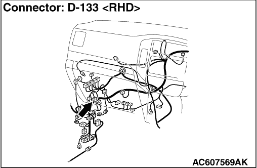
| note | Prior to the wiring harness inspection, check intermediate connector D-133 and repair
if necessary. |
- Check the input and output lines to the revolution detection sensor for open
or short circuit.
Q.
Is the check result normal?
STEP 10. Connector check: F-11 front power window sub switch (LH) connector
Q.
Is the check result normal?
STEP 11. Check the wiring harness from F-11 front power window sub switch (LH) connector terminal Nos. 2, 3, 8 to F-06 front power window motor (LH) connector terminal Nos. 2, 5,4.
- Check the input and output lines to the revolution detection sensor for open
or short circuit.
Q.
Is the check result normal?
STEP 12. Retest the system.
| (1)Replace the front power window sub switch (LH). |
| (2)Check that the front passenger’s power window anti-trap function works. |
Q.
Is the check result normal?
STEP 13. Connector check: F-26 rear power window motor (RH) connector
Q.
Is the check result normal?
STEP 14. Resistance measurement at the F-26 rear power window motor (RH) connector.
| (1)Disconnect the connector, and measure at the wiring harness side. |
| (2)Continuity between F-26 rear power window motor (RH) connector terminal No.6 and
body earth OK: Continuity exists (2 Ω or less) |
Q.
Is the check result normal?
STEP 15. Check the wiring harness from F-26 rear power window motor (RH) connector terminal No.6 to body earth.
| note | Prior to the wiring harness inspection, check intermediate connector E-43, and repair
if necessary. |
- Check the input and output lines to the revolution detection sensor for open
or short circuit.
Q.
Is the check result normal?
STEP 16. Connector check: F-23 rear power window sub switch (RH) connector
Q.
Is the check result normal?
STEP 17. Check the wiring harness from F-23 rear power window sub switch (RH) connector terminal Nos. 2, 3, 8 to F-26 rear power window motor (RH) connector terminal Nos. 2, 5, 4.
- Check the input and output lines to the revolution detection sensor for open
or short circuit.
Q.
Is the check result normal?
STEP 18. Retest the system.
| (1)Replace the rear power window sub switch (RH). |
| (2)Check that the rear right power window anti-trap function works. |
Q.
Is the check result normal?
STEP 19. Connector check: F-20 rear power window motor (LH) connector
Q.
Is the check result normal?
STEP 20. Resistance measurement at the F-20 rear power window motor (LH) connector.
| (1)Disconnect the connector, and measure at the wiring harness side. |
| (2)Continuity between F-20 rear power window motor (LH) connector terminal No.6 and
body earth OK: Continuity exists (2 Ω or less) |
Q.
Is the check result normal?
STEP 21. Check the wiring harness from F-20 rear power window motor (LH) connector terminal No.6 to body earth.
| note | Prior to the wiring harness inspection, check intermediate connector E-42, and repair
if necessary. |
- Check the input and output lines to the revolution detection sensor for open
or short circuit.
Q.
Is the check result normal?
STEP 22. Connector check: F-17 rear power window sub switch (LH) connector
Q.
Is the check result normal?
STEP 23. Check the wiring harness from F-17 rear power window sub switch (LH) connector terminal Nos. 2, 3, 8 to F-20 rear power window motor (LH) connector terminal Nos. 2, 5, 4.
- Check the input and output lines to the revolution detection sensor for open
or short circuit.
Q.
Is the check result normal?
STEP 24. Retest the system.
| (1)Replace the rear power window sub switch (LH). |
| (2)Check that the rear left power window anti-trap function works. |
Q.
Is the check result normal?