|
|
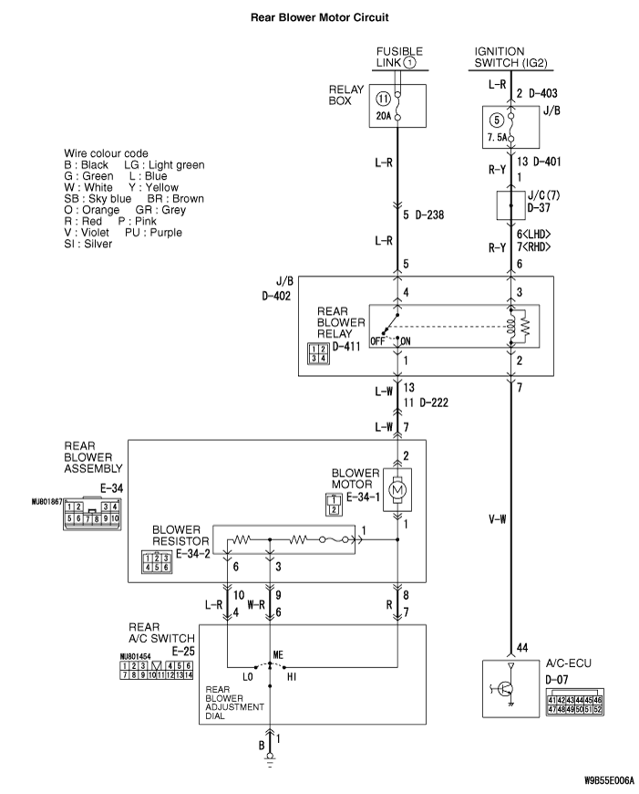
(1)Turn the ignition switch to the "ON" position.
|
|
|
(2)Turn the rear blower switch to the "3 (HI) " position.
|
|
|
Q.
Does the blower motor operate when the blower switch is moved to the "3 (HI) " position?
|
|
|
 Refer to Inspection procedure 11 "Air volume of rear blower cannot be changed <dual A/C> Refer to Inspection procedure 11 "Air volume of rear blower cannot be changed <dual A/C>  ." ."
|
|
|
|
|
|
Q.
Is the check result normal?
|
|
|
(1)Disconnect the connector, and measure at the wiring harness side.
|
|
|
(2)Turn the ignition switch to the "ON" position.
|
|
|
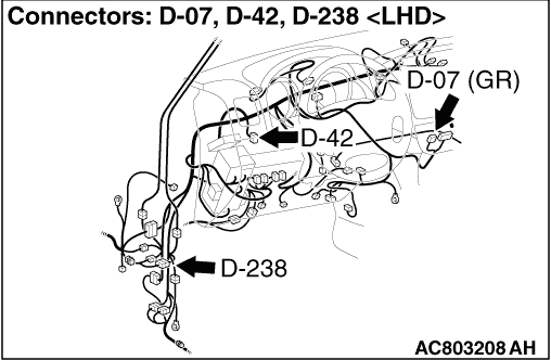
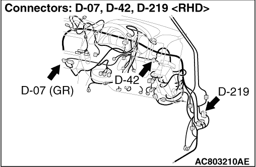
(3)Disconnect A/C-ECU connector D-07 and earth terminal 44.
|
|
|
(4)Measure the voltage between terminal 2 and body earth.
OK: System voltage
|
|
|
Q.
Is the check result normal?
|
|
|
Q.
Is the check result normal?
|
|
|
Q.
Is the rear blower relay in good condition?
|
|
|
 Replace the rear blower relay. Replace the rear blower relay.
|
|
|
|
|
|
(1)Remove the relay, and measure at the junction block side.
|
|
|
(2)Measure the voltage between terminal 4 and body earth.
OK: System voltage
|
|
|
Q.
Is the check result normal?
|
|
|
- Check the rear blower relay power supply line for open and short circuit.
|
|
|
Q.
Is the check result normal?
|
|
|
The trouble can be an intermittent malfunction (Refer to GROUP 00, How to Cope with Intermittent Malfunction ).
|
|
|
|
|
|
Repair the wiring harness.
|
|
|
|
|
|
(1)Remove the relay, and measure at the junction block side.
|
|
|
(2)Turn the ignition switch to the "ON" earth position.
|
|
|
(3)Voltage between terminal 3 and body earth.
OK: System voltage
|
|
|
Q.
Is the check result normal?
|
|
|
- Check the rear blower relay power supply line for open circuit.
|
|
|
Q.
Is the check result normal?
|
|
|
The trouble can be an intermittent malfunction (Refer to GROUP 00, How to Cope with Intermittent Malfunction ).
|
|
|
|
|
|
Repair the wiring harness.
|
|
|
|
|
|
- Check the rear blower relay power supply line for open circuit.
|
|
|
Q.
Is the check result normal?
|
|
|
Repair the wiring harness.
|
|
|
|
|
|
- Check the rear blower relay line for open and short circuit.
|
|
|
Q.
Is the check result normal?
|
|
|
The trouble can be an intermittent malfunction (Refer to GROUP 00, How to Cope with Intermittent Malfunction ).
|
|
|
|
|
|
Repair the wiring harness.
|
|
|
|
|
|
(1)Disconnect the connector, and measure at the wiring harness side.
|
|
|
(2)Turn the rear blower switch to the "3 (HI) " position.
|
|
|
(3)Continuity between terminal 1 and body earth.
OK: Continuity (Less than 2 Ω)
|
|
|
Q.
Is the check result normal?
|
|
|
Q.
Is the check result normal?
|
|
|
Q.
Is the rear blower relay in good condition?
|
|
|
Replace the rear blower relay.
|
|
|
|
|
|
(1)Disconnect the connector, and measure at the wiring harness side.
|
|
|
(2)Continuity between terminal 1 and body earth.
OK: Continuity (Less than 2 Ω)
|
|
|
Q.
Is the check result normal?
|
|
|
- Check the rear A/C switch earth line for open circuit.
|
|
|
Q.
Is the check result normal?
|
|
|
The trouble can be an intermittent malfunction (Refer to GROUP 00, How to Cope with Intermittent Malfunction ).
|
|
|
|
|
|
Repair or replace the wiring harness.
|
|
|
|
|
|
- Check the rear blower relay line for open and short circuit.
|
|
|
Q.
Is the check result normal?
|
|
|
The trouble can be an intermittent malfunction (Refer to GROUP 00, How to Cope with Intermittent Malfunction ).
|
|
|
|
|
|
Repair the wiring harness.
|
|
|
|
|
|
Q.
Is the rear blower motor in good condition?
|
|
|
Replace the rear blower motor.
|
|
|
|