REMOVAL AND INSTALLATION <2WD>


Pre-removal Operation
  • Fuel Line Pressure Reduction (Refer to GROUP 13A - On-vehicle Service, Reduce Pressurized Fuel Lines <4B1>, Refer to GROUP 13D - On-vehicle Service, Reduce Pressurized Fuel Lines <4A9>).
  • Draining Fuel
  • Exhaust Centre Pipe Removal (Refer to GROUP 15 - Exhaust Pipe and Main Muffler <4B1>, <4A9>).
  • Rear Seat Cushion Assembly Removal (Refer to GROUP 52A - Rear Seat Assembly ).

Post-installation Operation
  • Rear Seat Cushion Assembly Installation (Refer to GROUP 52A - Rear Seat Assembly ).
  • Exhaust Centre Pipe Installation (Refer to GROUP 15 - Exhaust Pipe and Main Muffler <4B1>, <4A9>).
  • Refilling Fuel
  • Checking for Fuel Leaks (Refer to ).


Removal steps
<<A>>

1.
Fuel tank pump and gauge assembly connector
<<A>>
>>D<<
2.
Fuel main pipe connection


3.
Fuel vapour hose (fuel vapour pipe side) connection


4.
Fuel filler neck breather hose (Fuel filler neck side) connection

>>C<<
5.
Fuel filler hose (fuel filler neck side) connection


6.
Parking brake rear cable clamp connection
<<B>>

7.
Fuel tank band
<<B>>

8.
Fuel tank assembly


9.
Fuel filler neck breather hose

>>B<<
10.
Fuel filler hose


11.
Fuel shut-off valve


12.
Fuel vapour hose


Removal steps


13.
Fuel tank bracket and connector housing assembly <Except 4B1 engine and 4A9 engine vehicles for Russia>


14.
Fuel pump bracket plate
<<C>>
>>A<<
15.
Fuel tank pump and gauge assembly


16.
Fuel tank pump and gauge assembly gasket


17.
Fuel tank lower protector


18.
Fuel tank

REMOVAL SERVICE POINTS


For removal service points, follow the same service procedures as 10 MY OUTLANDER.

INSTALLATION SERVICE POINTS


For service points other than below, follow the same service procedures as 10 MY OUTLANDER.

>>B<< FUEL FILLER HOSE CONNECTION


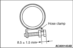
After connecting the fuel filler hose, tighten the bolts of hose clamp so that the tightening dimension is 8.5 ± 1.5 mm.

>>C<< FUEL FILLER HOSE (FUEL FILLER NECK SIDE) CONNECTION


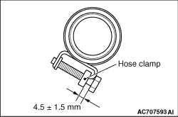
After connecting the fuel filler hose (fuel filler neck side), tighten the bolts of hose clamp so that the tightening dimension is 4.5 ± 1.5 mm.