REMOVAL AND INSTALLATION
| caution |
|

Pre-removal Operation
|
Post-installation Operation
|
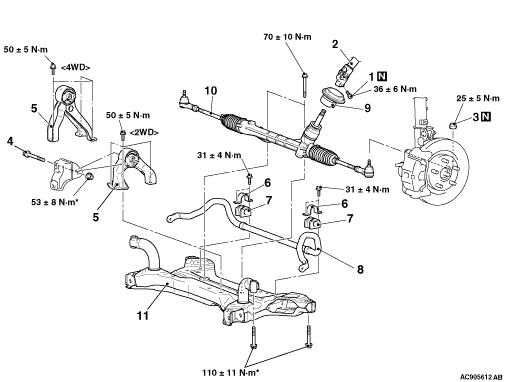 |
<LH drive vehicles>
|
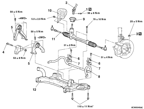 |
<RH drive vehicles>
|
REMOVAL SERVICE POINTS |
| For removal service points, follow the same service procedures as 10 MY OUTLANDER. |
INSTALLATION SERVICE POINTS |
| For service points other than below, follow the same service procedures as 10 MY OUTLANDER. |
>>C<< STEERING COLUMN SHAFT ASSEMBLY AND STEERING GEAR AND LINKAGE ASSEMBLY CONNECTION/STEERING COLUMN BOLT INSTALLATION |
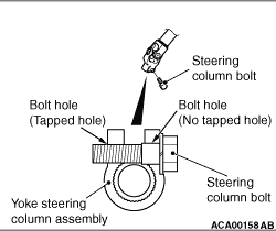 |
Insert the steering column bolt into the no-tapped bolt hole, and tighten it to the specified
torque. Tightening torque: 36 ± 6 N·m |