REMOVAL AND INSTALLATION
| caution | When the hydraulic unit (integrated with ASC-ECU)
is replaced, after turning the ignition switch ON or OFF (vehicle information from ETACS-ECU
is registered), always carry out the calibration of all sensors (steering wheel sensor, G and
yaw rate sensor, and brake fluid pressure sensor) at one time (Refer to  ). ). |
<LHD>
| note | ASC-ECU is located in the hydraulic unit. |
Pre-removal operation
|
Post-installation operation
|
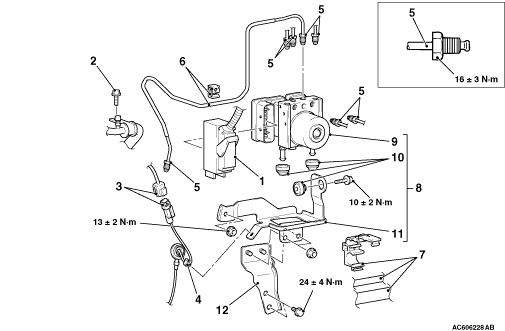 |
|
<RHD>
| caution | When the hydraulic unit (integrated with ASC-ECU)
is replaced, after turning the ignition switch ON or OFF (vehicle information from ETACS-ECU
is registered), always carry out the calibration of all sensors (steering wheel sensor, G and
yaw rate sensor, and brake fluid pressure sensor) at one time (Refer to ). |
| note | ASC-ECU is located in the hydraulic unit. |
Pre-removal operation
|
Post-installation operation
|
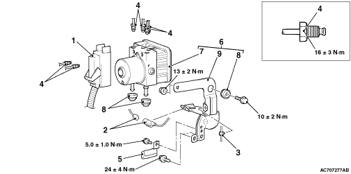 |
|
REMOVAL SERVICE POINTS |
| For removal service points, follow the same service procedures as 10 MY OUTLANDER. |
INSTALLATION SERVICE POINT |
| For installation service points, follow the same service procedures as 10 MY OUTLANDER. |