Code No.C1340
Stop lamp switch error


|
|
| caution |
- If there is
any problem in the CAN bus lines, an incorrect diagnosis code may be set. Prior to this diagnosis,
diagnose the CAN bus lines (Refer to GROUP 54C - CAN Bus Diagnostics Table
 ). ).
- Whenever ECU is replaced, ensure that the CAN bus lines are normal.
|
|
|
|
ASC-ECU monitors the ON/OFF signal from the stop lamp switch and the pressure
sensor (incorporated in the hydraulic unit).
|
|
|
DIAGNOSIS CODE SET CONDITIONS
|
|
|
This diagnosis code is set in the following case.
|
|
|
- When the vehicle has run for a long time with the stop lamp switch turned
ON.
- When the OFF status of the stop lamp switch does not match the vehicle attitude
|
|
|
- Improper adjustment of stop lamp switch installation position
- Stop lamp switch malfunction
- Damaged wiring harness and connectors
- ASC-ECU malfunction
|
|
|
STEP 1. M.U.T.-III CAN bus diagnostics
|
|
|
Use M.U.T.-III to diagnose the CAN bus lines.
|
|
|
Q.
Is the check result normal?
|
|
|
 Go to Step 3. Go to Step 3.
|
|
|
|
|
|
 Repair the CAN bus lines (Refer to GROUP 54C - CAN Bus Diagnostics Table ).
On completion, go to Step 2. Repair the CAN bus lines (Refer to GROUP 54C - CAN Bus Diagnostics Table ).
On completion, go to Step 2.
|
|
|
|
|
|
STEP 2. Diagnosis code recheck after resetting CAN bus lines
|
|
|
Q.
Is diagnosis code No.C1340 set?
|
|
|
Go to Step 3.
|
|
|
|
|
|
This diagnosis is complete.
|
|
|
|
|
|
STEP 3. Auxiliary battery check
|
|
|
Refer to GROUP 54A - Battery Test .
|
|
|
Q.
Is the battery in good condition?
|
|
|
Go to Step 4.
|
|
|
|
|
|
Charge or replace the auxiliary battery. Then go to Step 22.
|
|
|
|
|
|
STEP 4. Stop lamp operation check
|
|
|
Check the stop lamp operation when the brake pedal is depressed. Check that all the stop
lamp illuminates when the brake pedal is depressed and that it goes out when the brake pedal
is released.
|
|
|
OK:
When the brake pedal is released: OFF
When the brake pedal is depressed: Illuminates
|
|
|
Q.
Is the check result normal?
|
|
|
Go to Step 16.
|
|
|
|
|
|
Go to Step 5.
|
|
|
|
|
|
STEP 5. Check for stop lamp switch installation
|
|
|
Refer to GROUP 35A - On-vehicle Service/Brake Pedal Check and Adjustment .
|
|
|
Q.
Is the check result normal?
|
|
|
Go to Step 6.
|
|
|
|
|
|
Install the stop lamp switch correctly (Refer to GROUP 35A - On-vehicle
Service/Brake Pedal Check and Adjustment ). Then
go to Step 22.
|
|
|
|
|
|
STEP 6. Stop lamp switch continuity check
|
|
|
(1)Remove the stop lamp switch (Refer to GROUP 35A - Brake Pedal <LHD>, <RHD>).
|
|
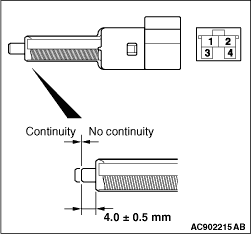
(2)Connect the circuit tester (Ω range) to the stop lamp switch connector terminals
No.1 and 2.
(3)Check for continuity between the terminals of the switch.
|
|
Check condition
|
Terminal connector of tester
|
Normal condition
|
At free position
|
1 - 2
|
Continuity exists
(2 Ω or less)
|
Press the plunger from the edge of the outer case by the dimension shown
in the figure.
|
1 - 2
|
No continuity
|
|
Q.
Is the check result normal?
Go to Step 7.
Replace the stop lamp switch (Refer to GROUP 35A - Brake Pedal <LHD>, <RHD>).
Then go to Step 22.
|
|
|
STEP 7. Relay box fuse No.8 check
|
|
|
Q.
Is the check result normal?
|
|
|
Go to Step 12.
|
|
|
|
|
|
Go to Step 8.
|
|
|
|
|
|
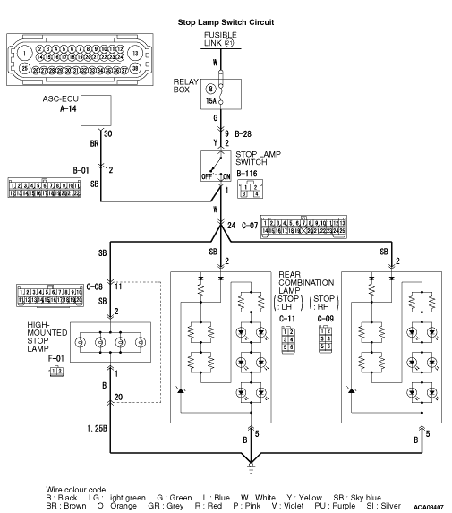
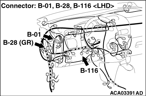
STEP 8. Connector check: B-28 intermediate connector, B-116 stop lamp
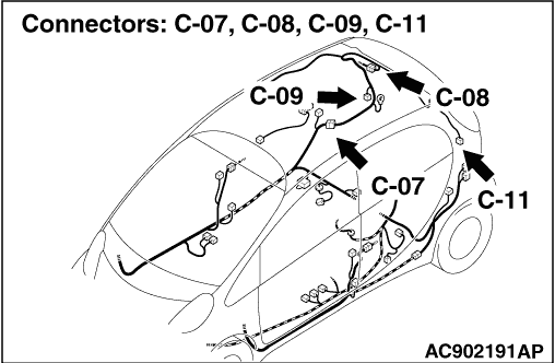
switch connector, B-01 intermediate connector, C-07 intermediate connector, C-09 rear combination
lamp (stop: RH) connector, C-11 rear combination lamp (stop: LH) connector , C-08 intermediate connector,
F-01 high-mounted stop lamp connector, A-14 ASC-ECU connector
|
|
|
Q.
Is the check result normal?
|
|
|
Go to Step 9.
|
|
|
|
|
|
Repair the damaged connector, and then replace fuse No.8. Then go to Step 22.
|
|
|
|
|
|
STEP 9. Resistance measurement at B-116 stop lamp switch connector
|
|
|
(1)Disconnect B-116 stop lamp switch connector, and measure at the wiring harness
side.
|
|
|
(2)Disconnect B-28 intermediate connector.
|
|
|
(3)Measure the resistance between the terminal No.2 and the body earth.
OK: No continuity
|
|
|
Q.
Is the check result normal?
|
|
|
Go to Step 10.
|
|
|
|
|
|
An short to power supply line may be present in the wiring harness between B-28
intermediate connector terminal No.9 and B-116 stop lamp switch connector terminal No.2. Repair
the wiring harness, and then replace fuse No.8. Then go to Step 22.
|
|
|
|
|
|
STEP 10. Resistance measurement at B-116 stop lamp switch connector
|
|
|
(1)Disconnect B-116 stop lamp switch connector, and measure at the wiring harness
side.
|
|
|
(2)Disconnect A-14 ASC-ECU connector and B-01 intermediate connector.
|
|
|
(3)Measure the resistance between the terminal No.1 and the body earth.
OK: No continuity
|
|
|
Q.
Is the check result normal?
|
|
|
Go to Step 11.
|
|
|
|
|
|
An short circuit may be present in the wiring harness between B-116 stop lamp
switch connector terminal No.1 and A-14 ASC-ECU connector terminal No.30, or between B-116 stop
lamp switch connector terminal No.1 and B-01 intermediate connector terminal No.11. Repair the
wiring harness, and then replace fuse No.8. Then go to Step 22.
|
|
|
|
|
|
STEP 11. Resistance measurement at C-07 intermediate connector
|
|
|
(1)Disconnect C-07 intermediat connector, and measure at the wiring harness side.
|
|
|
(2)Disconnect C-09 rear combination lamp (stop: RH) connector, C-11 rear combination
lamp (stop: LH) connector, C-08 intermediat connector, F-01 high- mounted stop lamp connector.
|
|
|
(3)Measure the resistance between the terminal No.24 and the body earth.
OK: No continuity
|
|
|
Q.
Is the check result normal?
|
|
|
Replace fuse No.42. Then go to Step 22.
|
|
|
|
|
|
An short circuit may be present in the wiring harness between C-07 intermediat
connector terminal No.24 and C-09 rear combination lamp (stop: RH) connector terminal No.2 or
C-11 rear combination lamp (stop: LH) connector terminal No.2 or C-08 intermediat connector
terminal No.11 or F-01 high-mounted stop lamp connector terminal No.2. Repair the wiring harness,
and then replace fuse No.8. Then go to Step 22.
|
|
|
|
|
|
STEP 12. Connector check: B-28 intermediat connector, B-01 intermediat
connector, B-116 stop lamp switch connector, A-14 ASC-ECU connector
|
|
|
Q.
Is the check result normal?
|
|
|
Go to Step 13.
|
|
|
|
|
|
Repair the damaged connector. Then go to Step 22.
|
|
|
|
|
|
STEP 13. Measure the voltage at the B-28 intermediate connector.
|
|
|
| caution |
Measure while the brake pedal is not depressed.
|
|
|
|
Measure the voltage between terminal No.9 and the body earth by backprobing.
|
|
|
OK: Approximately system voltage
|
|
|
Q.
Is the check result normal?
|
|
|
Go to Step 14.
|
|
|
|
|
|
An open circuit may be present in the wiring harness between B-28 intermediat
connector terminal No.9 and fusible link No.21. Repair the wiring harness. Then go to Step 22
.
|
|
|
|
|
|
STEP 14. Measure the voltage at B-116 stop lamp switch connector.
|
|
|
(1)Disconnect B-116 stop lamp switch connector, and measure the voltage at harness
connector side.
|
|
|
(2)Measure the voltage between the terminal No.2 and the body earth.
OK: Approximately system voltage
|
|
|
Q.
Is the check result normal?
|
|
|
Go to Step 15.
|
|
|
|
|
|
An open circuit may be present in the wiring harness between B-116 stop lamp switch
connector terminal No.2 and B-28 intermediat connector terminal No. 9. Repair the wiring harness.
Then go to Step 15.
|
|
|
|
|
|
STEP 15. Measure the voltage at C-09 rear combination lamp (stop:
RH) connector, C-11 rear combination lamp (stop: LH) connector, F-01 high-mounted stop lamp connector
.
|
|
|
(1)Disconnect C-09 rear combination lamp (stop: RH) connector, C-11 rear combination
lamp (stop: LH) connector, F-01 high-mounted stop lamp connector, and measure the voltage at
harness connector side.
|
|
|
(2)Brake pedal is release.
|
|
|
(3)Measure the voltage between the C-09 rear combination lamp (stop: RH) connector
terminal No.2, C-11 rear combination lamp (stop: LH) connector terminal No.2, F-01 high-mounted
stop lamp connector terminal No.2 and the body earth.
OK: Approximately system voltage
|
|
|
Q.
Is the check result normal?
|
|
|
Go to Step 17.
|
|
|
|
|
|
An open circuit may be present in the wiring harness between C-07 intermediat
connector terminal No.24 and C-09 rear combination lamp (stop: RH) connector terminal No.2,
C-11 rear combination lamp (stop: LH) connector terminal No.2, F-01 high-mounted stop lamp connector
terminal No.2. Repair the wiring harness. Then go to Step 22.
|
|
|
|
|
|
STEP 16. Connector check: A-14 ASC-ECU connector
|
|
|
Q.
Is the check result normal?
|
|
|
Go to Step 17.
|
|
|
|
|
|
Repair the damaged connector. Then go to Step 22.
|
|
|
|
|
|
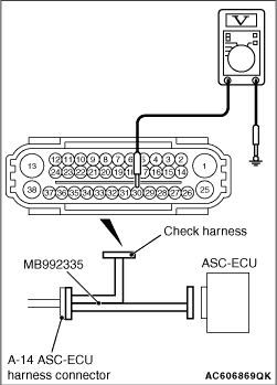
STEP 17. Measure the voltage at the A-14 ASC-ECU connector.
|
|
(1)Disconnect the ASC-ECU connector, connect special tool ABS check harness (MB992335)
to the harness-side connector, and then measure the voltage at the special tool connector side.
| note |
Do not connect the special tool ABS check harness (MB992335) to ASC-ECU.
|
(2)Turn the electric motor switch to the "ON" position.
(3)Measure the voltage between the terminal No.30 and the body earth.
OK:
When the brake pedal is released: 1 V or less
When the brake pedal is depressed: Approximately system voltage
Q.
Is the check result normal?
Go to Step 18.
An open circuit may be present in the wiring harness between B-116 stop lamp switch
connector terminal No.1 and A-14 ASC-ECU connector terminal No.30. Repair the wiring harness.
Then go to Step 22.
|
|
|
STEP 18. Measure the voltage at B-116 stop lamp switch connector.
|
|
|
(1)Disconnect B-116 stop lamp switch connector, and measure the voltage at harness
connector side.
|
|
|
(2)Turn the electric motor switch to the "ON" position.
|
|
|
(3)Measure the voltage between the terminal No.1 and the body earth.
OK: Approximately system voltage
|
|
|
Q.
Is the check result normal?
|
|
|
Go to Step 20.
|
|
|
|
|
|
An open circuit may be present in the wiring harness between B-116 stop lamp switch
connector terminal No.1 and A-14 ASC-ECU connector terminal No.30. Repair the wiring harness.
Then go to Step 19.
|
|
|
|
|
|
STEP 19. Resistance measurement at B-116 stop lamp switch connector
|
|
|
(1)Disconnect B-116 stop lamp switch connector, and measure at the wiring harness
side.
|
|
|
(2)Disconnect A-14 ASC-ECU connector.
|
|
|
(3)Measure the resistance between the terminal No.1 and the body earth.
OK: No continuity
|
|
|
Q.
Is the check result normal?
|
|
|
Go to Step 20.
|
|
|
|
|
|
An short circuit may be present in the wiring harness between B-116 stop lamp
switch connector terminal No.1 and A-14 ASC-ECU connector terminal No.30. Repair the wiring
harness. Then go to Step 20.
|
|
|
|
|
|
STEP 20. Resistance measurement at B-116 stop lamp switch connector
|
|
|
(1)Disconnect B-116 stop lamp switch connector, and measure at the wiring harness
side.
|
|
|
(2)Measure the resistance between the terminal No.1 and the body earth.
OK: Continuity
|
|
|
Q.
Is the check result normal?
|
|
|
Go to Step 21.
|
|
|
|
|
|
An open circuit may be present in the wiring harness between B-116 stop lamp switch
connector terminal No.1 and body earth. Replace the wiring harness. Then go to Step 22.
|
|
|
|
|
|
STEP 21. Diagnosis code recheck
|
|
|
Erase the diagnosis code.
|
|
|
Q.
Is diagnosis code No.C1340 set?
|
|
|
Replace the hydraulic unit (integrated with ASC-ECU) (Refer to ).
Then go to Step 22.
|
|
|
|
|
|
Intermittent malfunction (Refer to GROUP 00 - How to Use Troubleshooting/How
to Cope with Intermittent Malfunctions ).
|
|
|
|
|
|
STEP 22. Diagnosis code recheck
|
|
|
Erase the diagnosis code.
|
|
|
Q.
Is diagnosis code No.C1340 set?
|
|
|
Return to Step 1.
|
|
|
|
|
|
This diagnosis is complete.
|
|
|
|