|
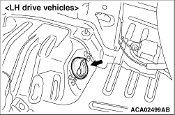
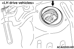
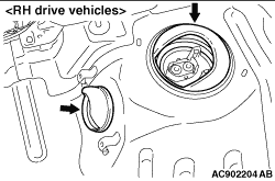
Disengage the hook of the rubber boot and push it out of the vehicle (towards under the
vehicle).
|
|
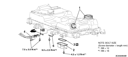
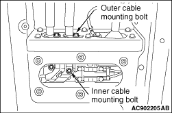
1.Remove the inner cable mounting bolts (2 locations).
2.Remove the outer cable mounting bolts (2 locations).
3.Pull out the cable from the main battery.
|
|
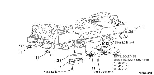
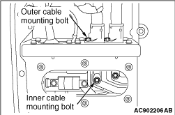
1.Remove the inner cable mounting bolts (2 locations).
2.Remove the outer cable mounting bolts (2 locations).
3.Pull out the cable from the main battery.
|
|
|
1.Attach the removed work hole lid and O-ring to the main battery so that no water,
foreign material, etc. enter the inside of the main battery.
|
|
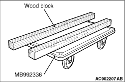
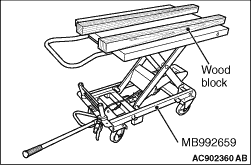
2.Use the following special tools and 2 wood blocks (100 x 100 x 1500 mm).
(1)
Remove the handle of the EV battery cart (special tool: MB992336) and set the wood blocks.
(2)
When the vehicle is lowered with the lift using the above special tool (MB992336), if
the lower stopper lock does not work, use the EV battery lifting cart (special tool: MB992659)
instead.
|
|
| note |
For how to use the EV battery lifting cart in detail, refer to the provided "Operation
Manual".
|
|
3.With the main battery installed on the vehicle, remove the mounting bolts (2 at front
and 2 at rear of the main battery).
4.Loosen the remaining mounting bolts (6 locations).
|
|
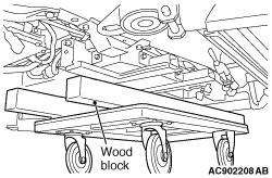
5.Lower the vehicle with the lift until just before the bottom of the main battery contacts
the wood block.
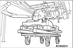
6.Remove all the mounting bolts on the main battery.
|
|
7.
| caution |
Be careful of damage due to wiring harness caught or hooked.
|
Raise the vehicle with the lift and remove the main battery.
|
|
8.
| danger |
- Store the main battery on a place with no
risk of wetting.
- Do not bring the main battery close to fire or heat it to 60°C or more.
|
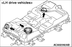
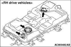
Cover around the air outlet of the main battery (computer unit portion) with a vinyl sheet
or others so that no water, foreign material, etc. enter the inside of the main battery.
|
|
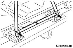
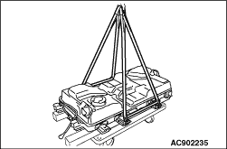
9.When moving the removed main battery with a crane or others, use the EV battery sling
tool kit (special tool: MB992343) to sling it up in accordance with the following procedure.
- EV battery sling tool kit (MB992343)
- Eye bolts (MB992344 x 4)
- EV battery sling belts (MB992345 x 2)
- Washers (MF450156 x 8)
- Hexagon nuts (MU001480 x 4)
| note |
For how to use the EV battery sling belt in detail, refer to the provided "Operation Manual".
|
(1)
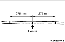
Mark the centre of the EV battery sling belt (MB992345) and positions 275 mm right and
left from the centre.
|
|
| note |
The marking is intended for alignment of the EV battery sling belt and eye bolt.
|
|
(2)
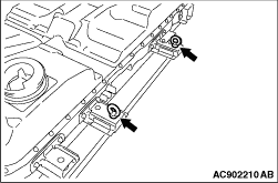
Install the eye bolts (MB992344), washers (MF450156) and nuts (MU001480) onto the positions
(2 each at the right and left) on the main battery as shown in the figure.
(3)
Pass the EV battery sling belt through the eye bolts and align the marks on the EV battery
sling belt to the eye bolt positions.
(4)
Bind 2 EV battery sling belts together and sling up the main battery with a crane or others.
|
|
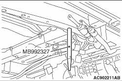
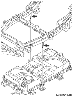
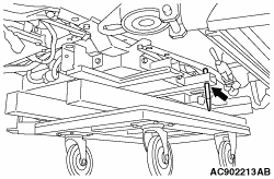
1.Install the EV battery guide (special tool: MB992327) onto the 2 main battery installation
positions on the vehicle.
|
|
2.
| caution |
Be careful of damage due to wiring harness caught or hooked.
|
Lower the vehicle with the lift while checking the relative positions of the EV battery
guide installed on the vehicle and installation hole for the main battery.
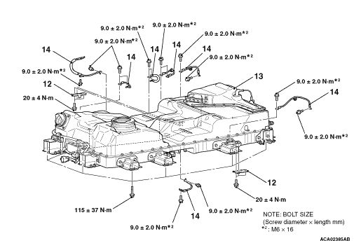
3.Temporarily tighten the main battery mounting bolts other than those for the EV battery
guide installation.
4.Remove the EV battery guide from the vehicle and temporarily tighten the mounting
bolts.
5.Tighten all the mounting bolts to the specified torque.
Tightening torque: 115 ± 37 N·m
|
|
|
1.Remove the sealant adhering to the floor frame plate mounting bolts, main battery,
and vehicle.
|
|
|
2.Apply the sealant to the threads of the floor frame plate mounting bolts.
Sealant: ThreeBond 1324N
| note |
After applying the sealant, immediately install the mounting bolts.
|
|
|
|
3.
| caution |
After installing the part, do not apply oil or water
on the sealant applied area or activate the electric motor unit until a sufficient time (1 hour
or longer) has passed.
|
Tighten the floor frame plate mounting bolts to the specified torque.
Tightening torque: 20 ± 4 N·m
|
|
|
1.Apply the specified grease to the O-ring and install it to the cable.
Grease: Niglube RM
|
|
|
2.Install the cable onto the main battery.
|
|
|
3.Install the outer cable mounting bolts and inner cable mounting bolts in this order
and tighten them to the specified torque.
Tightening torque: 7.0 ± 3.0 N·m
|
|
|
1.Temporarily tighten each mounting bolt on the work hole lid.
|
|
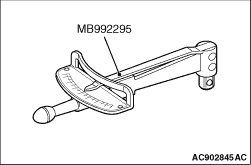
2. Using the torque wrench (special tool: MB992295), tighten 2 mounting bolts at the centre
to the specified torque respectively.
Tightening torque: 4.2 ± 1.2 N·m
3. Using the special tool, tighten the remaining mounting bolts to the specified torque
respectively.
Tightening torque: 4.2 ± 1.2 N·m
|