REMOVAL AND INSTALLATION


Pre-removal operation
  • Steering wheel removal (Refer to GROUP 37 - Steering Wheel ).
  • Lower panel assembly, driver’s side under cover <Except vehicles Single cab>, steering column cover removal (Refer to GROUP 52A - Instrument Panel Assembly ).

Post-installation operation
  • Lower panel assembly, driver’s side under cover <Except vehicles Single cab>, steering column cover installation (Refer to GROUP 52A - Instrument Panel Assembly ).
  • Steering wheel installation (Refer to GROUP 37 - Steering Wheel ).
  • Key Interlock and Shift Lock Mechanism Check (Refer to ).


Removal steps

>>A<<
1.
Key interlock cable connection


2.
Key interlock actuator ECU

INSTALLATION SERVICE POINTS


>>A<< KEY INTERLOCK CABLE CONNECTION


1.Turn the ignition switch to the ACC position.
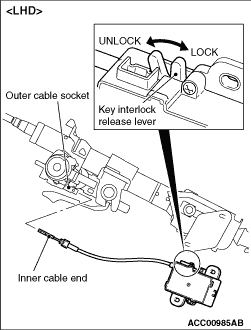
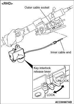

2.
caution Make sure that the key interlock release lever is set into UNLOCK position.
Insert the inner cable end into the outer cable socket.
3.Check that the key interlock cable lug is engaged in the outer cable socket square hole, and then turn the ignition switch to the LOCK (OFF) position to retain the inner cable end.


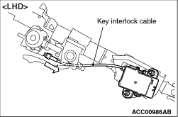
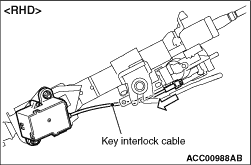
4.Check that the key interlock cable is retained securely by pulling it into the arrow direction.