REMOVAL AND INSTALLATION


warning
  • For vehicles with SRS, before removing the steering wheel and driver’s air bag module assembly, refer to GROUP 52B, Service Precautions () and Driver’s Air Bag Module(s) and Clock Spring ().
  • For vehicles with SRS, when removing and installing the steering wheel, do not let it bump against the air bag module.
  • After the installation, perform a calibration for the ASTC-ECU to learn the steering wheel sensor neutral point. (Refer to GROUP 35C - On-vehicle Service - Steering Wheel Sensor Calibration ).<Vehicles with ASTC>
Post-installation Operation
  • Checking Steering Wheel Position with Wheels Straight Ahead
  • Steering Wheel Play Check (Refer to ).


Removal steps
<<A>>

1.
Cover

>>B<<
2.
Horn connector connection
<<B>>
>>B<<
3.
Driver’s air bag module connector connection
<<C>>

4.
Driver’s air bag module assembly


5.
Steering wheel pad assembly


6.
Flange nut
<<D>>
>>A<<
7.
Steering wheel


Removal steps
<<A>>

1.
Cover

>>B<<
2.
Horn connector connection

>>B<<
3.
Steering switch connector connection
<<B>>
>>B<<
4.
Driver’s air bag module connector connection


5.
Steering wheel voice control switch connector connection <Vehicles with steering wheel voice control switch>


6.
Steering wheel voice control switch cover <Vehicles with steering wheel voice control switch>


7.
Steering wheel voice control switch <Vehicles with steering wheel voice control switch>
<<C>>

8.
Driver’s air bag module


9.
Steering wheel upper cover (RH) <Vehicles without cruise control switch>


10.
Steering wheel cruise control switch connector connection <Vehicles with cruise control switch>


11.
Steering wheel cruise control switch <Vehicles with cruise control switch>


12.
Steering wheel upper cover (LH) <Vehicles without steering wheel audio remote control switch>


13.
Steering wheel audio remote control switch connector connection<Vehicles with steering wheel audio remote control switch>


14.
Steering wheel audio remote control switch<Vehicles with steering wheel audio remote control switch>


15.
Flange nut
<<D>>
>>A<<
16.
Steering wheel assembly

REMOVAL SERVICE POINTS


<<A>> COVER REMOVAL


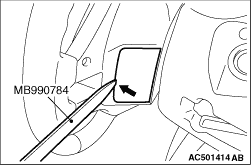
Insert special tool ornament remover (MB990784) at the indicated position to remove the cover.
note The special tool can be inserted through the notch behind the area shown.

<<B>>DRIVER’S AIR BAG MODULE CONNECTOR DISCONNECTION


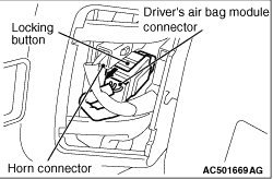
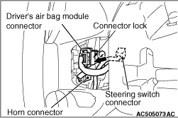
<Vehicles with 4-spoke type steering wheel>
    Disconnect the driver’s air bag module connector while compressing its locking button and sliding it to the direction of an arrow.

<Vehicles with 3-spoke type steering wheel>
    Disconnect the connector while sliding the part shown in the figure (connector lock) of the driver’s air bag module connector in the direction of an arrow.

<<C>> DRIVER’S AIR BAG MODULE REMOVAL


caution
  • Never use an electric tester to diagnose the air bag module circuit. Never attempt to disassemble the air bag module.
  • Be sure to store the removed air bag module in a clean and dry place with a pad surface facing upward.

<<D>> STEERING WHEEL REMOVAL


caution Make sure that use the special tool to remove the steering wheel. Otherwise the steering column shaft assembly shock absorbing mechanism will be damaged.
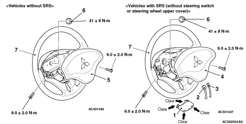
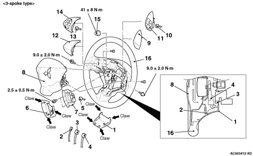
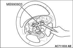
1.Position the steering wheel in the straight-ahead position.

2.Use special tool steering wheel puller (MB990803) to remove the steering wheel.

INSTALLATION SERVICE POINTS


>>A<< STEERING WHEEL INSTALLATION


After centring the clock spring (Refer to GROUP 52B - Air Bag Module Clock Spring ), install the steering wheel.

>>B<< DRIVER’S AIR BAG MODULE CONNECTOR / STEERING SWITCH CONNECTOR / HORN CONNECTOR CONNECTION


Connect the connector securely and route the harnesses not to lie off the cover hole.