|
|
Check that the function type is set as 1 or 3 in the service mode. (Refer to  .) .)
|
|
|
Q.
Is the check result satisfactory?
|
|
|
 Set the function type again in the service mode, and recheck the trouble symptom. Set the function type again in the service mode, and recheck the trouble symptom.
|
|
|
|
|
|
Use the M.U.T-III to diagnose the CAN bus lines.
|
|
|
Q.
Is the check result satisfactory?
|
|
|
Repair the CAN bus lines (Refer to GROUP 54C, Diagnosis - Can Bus Diagnostics
Table ). After diagnosing the CAN bus lines, go to Step
3.
|
|
|
|
|
|
Check whether the DIESEL system-related diagnosis code is set.
|
|
|
Q.
Is the diagnosis code set?
|
|
|
 Diagnose DIESEL system. (Refer to GROUP 13A -, Troubleshooting .)
After diagnosing the DIESEL system, go to Step 4. Diagnose DIESEL system. (Refer to GROUP 13A -, Troubleshooting .)
After diagnosing the DIESEL system, go to Step 4.
|
|
|
|
|
|
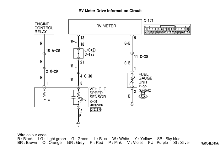
When the ignition switch is turned to the "LOCK" (OFF) position, check that the RV meter
does not set the diagnosis code.
|
|
|
Q.
Is the diagnosis code set?
|
|
|
Refer to diagnosis code chart .
|
|
|
|
|
|
Check whether the speedometer works normally.(Refer to .)
|
|
|
Q.
Does the speedometer work normally?
|
|
|
Diagnose the combination meter. (Refer to Combination meter - Troubleshooting .)
|
|
|
|

|
Q.
Is the check result normal?
Go to Step 7
Repair the defective connector.
|
|
- Check the signal line circuit for open circuit and short circuit.
Q.
Is the check result normal?
Go to Step 8
Repair the wiring harness.
|
|
Q.
Is the check result normal?
Go to Step 9
Repair the defective connector.
|
|
|
Check the fuel gauge unit .
|
|
|
Q.
Is the check result normal?
|
|
|
Replace the fuel gauge unit.
|
|
|
|
|
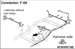
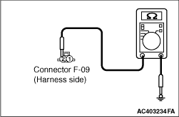
(1)Disconnect the connector, and measure at the wiring harness side.
|
|
(2)Measure the resistance between F-09 fuel gauge unit connector terminal No.2 and body earth
OK: Continuity exists (2 Ω or less)
Q.
Is the check result normal?
Go to Step 12
Go to Step 11
|
|
- Check the earth wires for open circuit.
Q.
Is the check result normal?
Retest the system.
Repair the wiring harness.
|
|
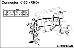
| note |
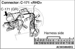
Prior to the wiring harness inspection, check the intermediate connector C-30, and repair
if necessary.
|
- Check the input line circuit for open circuit and short circuit.
Q.
Is the check result normal?
Go to Step 13
Repair the wiring harness.
|
|
|
Q.
Is a malfunction eliminated?
|
|
|
If no malfunctions are found in all steps, an intermittent malfunction is suspected.
Refer to GROUP 00, How to Use Troubleshooting/Inspection Service Points - How
to Cope with Intermittent Malfunction .
|
|
|
|