|
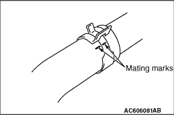
Make mating marks on the radiator hose and the hose clamp. Disconnect the radiator hose.
|


|
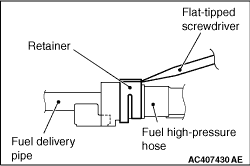
1.Follow the steps below to unlock the fuel high-pressure hose connector.
(1)
Insert a flat-tipped screwdriver (6 mm wide and 1 mm thick) into the retainer of the fuel
high-pressure hose connector.
(2)
|
|
| caution |
When pushing up the retainer of the fuel high-pressure hose connector, pay attention to
avoid damage to the retainer.
|
|
Turn the flat-tipped screwdriver inserted into the retainer by 90 degrees to push up the
retainer and unlock the fuel high-pressure hose connector.
2.Remove the fuel high-pressure hose.
|

|
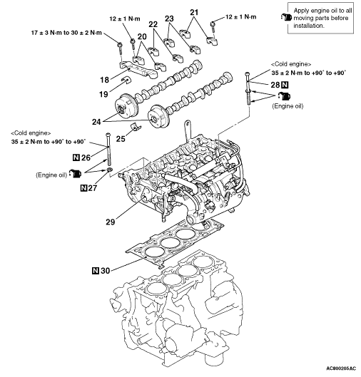
Loosen the mounting bolts of front camshaft bearing cap in the order of number shown in
the figure, and remove the front camshaft bearing cap assembly.
|

|
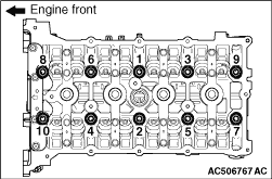
Loosen the mounting bolts of the camshaft bearing caps in the order of number shown in
the figure in four or five steps, and remove the camshaft bearing caps.
|
|
|
1.Temporarily install the engine oil pan which was removed at the timing chain removal
(Refer to  ). ).
|
|
|
2.Place a garage jack against the engine oil pan with a piece of wood in between to
support the engine and transmission assembly.
|
|
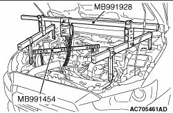
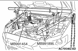
3.Remove special tool engine hanger (MB991928 or MB991895) which was installed for supporting
the engine and transmission assembly when the timing chain was removed
|

|
4.Loosen and remove the bolts in two or three steps in the order of number shown in the
figure.
|
|
1.
| caution |
Do not allow any foreign materials get into the coolant passages, oil
passages and cylinder.
|
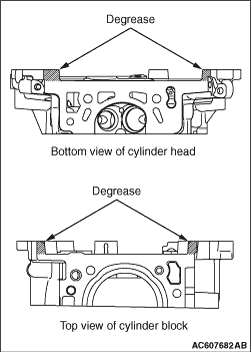
Remove the sealant and grease on the top surface of cylinder block and on the bottom surface
of the cylinder head. Then, use the quick-drying degreasing agent (white gasoline) to degrease
the sealant application surface.
|
|
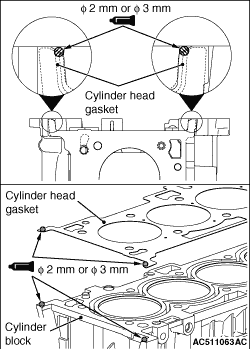
2.Apply the sealant to the top surface of cylinder block as shown in the figure.
Specified sealant: Three bond 1217G
3.Within three minutes after the sealant application, install the cylinder head gasket
to the cylinder block.
| note |
When the cylinder gasket is installed to the cylinder block, check that the sealant is
securely applied to the bead line of the cylinder head gasket.
|
4.Apply the sealant to the top surface of cylinder head gasket as shown in the figure.
Specified sealant: Three bond 1217G
5.
| caution |
After the installation, until a sufficient period of
time (one hour or more) elapses, do not apply the oil or water to the sealant application area
or start the engine.
|
Within three minutes after the sealant application, install the cylinder head assembly.
|
|
|
1.Replace the cylinder head bolt and washer with new ones.
|
|
|
2.For two bolts of the timing chain side, the washer can be removed from the bolt. Install
the washer, with its sag facing upward, to the bolts.
|
|
|
3.Apply a small amount of engine oil to the thread of the bolts and to the washers.
|

|
4.Tighten the bolts by the following procedure (plastic region angular tightening method).
(1)
Tighten the bolts to 35 ± 2 N·m in the order of number shown in the
figure.
(2)
|
|
| caution |
- When the tightening angle is smaller than
the specified tightening angle, the appropriate tightening capacity cannot be secured.
- When the tightening angle is larger than the specified tightening angle, remove
the bolt to start from the beginning again according to the procedure.
|
|
Apply paint marks to the head of cylinder head bolt and the cylinder head.
(3)
Tighten the cylinder head to 90° in the tightening order. Additionally tighten
to 90°, and check that the paint mark on the cylinder head bolt is aligned with the paint
mark on the cylinder head.
|
|
5.Install special tool engine hanger (MB991928 or MB991895) which was installed for supporting
the engine and transmission assembly when the timing chain was removed (Refer to ).
6.Remove the garage jack which supports the engine and transmission assembly.
7.Remove the engine oil pan installed temporarily.
|


|
When replacing the camshaft bearing, according to the identification mark of front camshaft
bearing cap in the table below, select a camshaft bearing with the corresponding size. Note
that the identification mark of camshaft bearing is stamped on the place shown in the figure.
|
|
Front camshaft bearing cap
|
Camshaft bearing identification mark
|
Identification mark
|
Journal diameter mm
|
1
|
40.000 - 40.008
|
1
|
2
|
40.008 - 40.016
|
2
|
3
|
40.016 - 40.024
|
3
|
|
|

|
1.Install the camshaft bearing caps to the cylinder heads.
| note |
Because the thrust camshaft bearing cap and camshaft bearing cap are the same in shape,
check the bearing cap number and additionally its symbol to identify the inlet and exhaust sides
for correct installation.
|
2.Tighten each camshaft bearing cap mounting bolt to the specified torque in the order
of number shown in the figure in two or three steps.
Tightening torque: 12 ± 1 N·m
|

|
1.
| caution |
When the mounting bolts are tightened with the front camshaft bearing
cap tilted, the front camshaft bearing cap is damaged. Install the front camshaft bearing cap
properly to the cylinder head and camshaft.
|
Install the front camshaft bearing cap to the cylinder head, and temporarily tighten the
front camshaft bearing cap to the specified torque in the order of the figure (1).
Tightening torque: 17 ± 3 N·m
2.Tighten the front camshaft bearing cap again to the specified torque in the order
of the figure (2).
Tightening torque: 30 ± 2 N·m
|

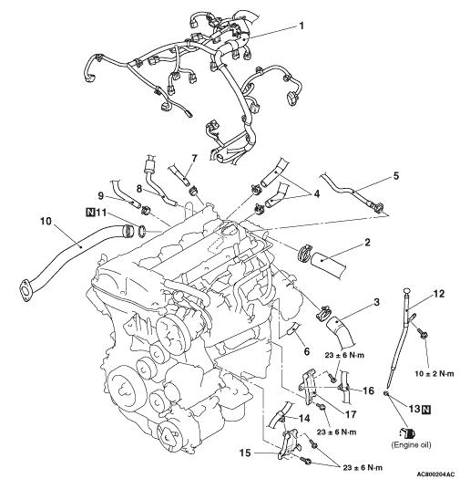
|
| caution |
Avoid adhesion of engine oil or grease to the O-ring.
|
Fit the O-ring in the water inlet pipe groove, wet the O-ring circumference or the pipe
mounting area inner wall, and then insert the O-ring.
|

|
1.
| caution |
- When pushing in the
retainer of the fuel high-pressure hose connector, pay attention to avoid damage to the retainer.
- After the installation of the fuel high-pressure hose, slightly pull the fuel high-pressure
hose to check that it is connected securely. At this time, also check that there is approximately
1-mm play.
|
Securely insert the fuel delivery pipe stopper into the fuel high-pressure hose connector
groove to install the fuel high-pressure hose to the fuel delivery pipe.
2.Push in the retainer of the fuel high-pressure hose connector to lock the fuel high-pressure
hose and fuel delivery pipe.
|

|
1.Insert radiator hose as far as the projection of the water inlet fitting or water outlet
fitting.
2.Align the mating marks on the radiator hose and hose clamp, and then connect the radiator
hose.
|