|
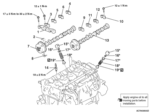
Loosen the mounting bolts of front camshaft bearing cap in the order of number shown in the figure, and remove the front camshaft bearing cap assembly.
|

|
Loosen the mounting bolts of the camshaft bearing caps in the order of number shown in the figure in four or five steps, and remove the camshaft bearing caps.
|

|
Remove all of the valve tappets by hand.
|

|
1.Screw in special tool retainer holder attachment (MB992090) to special tool valve spring compressor (MD998772), and assemble special tool retainer holder C (MB992089).
2.
| caution |
When removing the valve spring retainer lock, leave the piston of the cylinder in the TDC (Top Dead Centre) position. The valve may fall into the cylinder if the piston is not properly in the TDC position.
|
Install special tool MD998772 (with special tools MB992090 and MB992089 attached) to the cylinder head and compress the valve spring. Then, remove the valve spring retainer lock.
|

|
Use special tool valve stem seal pliers (MB992085) to nip the base of the stem seal (where the outside diameter is larger) securely, and remove it by twisting it to the left and right.
|
|
1.
| caution |
- Valve stem seals cannot be reused.
- Do not damage the wall of the tappet hole when installing the valve stem seal.
- Special tool valve stem seal installer (MD998737) must be used to install the valve stem seal. Improper installation of the valve stem seal could result in oil leaking past the valve guide.
|
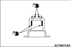
Apply a small amount of engine oil to the press-fit part and lip part of the new valve stem seal.
|
|
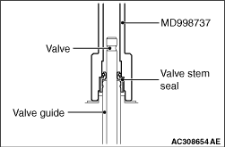
2.Use special tool valve stem seal installer (MD998737) to press-fit a new valve stem seal in the valve guide using the valve stem area as a guide.
|

|
Install the valve spring so that the painted side faces toward the camshaft.
|
|
In the same manner as removal, use special tool valve spring compressor (MD998772) with special tool retainer holder attachment (MB992090) and special tool retainer holder C (MB992089) attached to compress the valve spring, and install the valve spring retainer lock.
|
|
|
1.Apply a small amount of engine oil to the valve tappets.
|
|
2.
| caution |
Be sure to install the valve tappets in the same position as before.
|
Install the valve tappet to the cylinder head.
|

|
1.Install the camshaft bearing caps to the cylinder heads.
| note |
Because the thrust camshaft bearing cap and camshaft bearing cap are the same in shape, check the cap number and additionally its symbol to identify the inlet and exhaust sides for correct installation.
|
2.Tighten each camshaft bearing cap to the specified torque in the order of number shown in the figure in two or three steps.
Tightening torque: 12 ± 1 N·m
|


|
When replacing the camshaft bearing, according to the identification mark of front camshaft bearing cap in the table below, select a camshaft bearing with the corresponding size. Note that the identification mark of camshaft bearing is stamped on the place shown in the figure.
|
|
Front camshaft bearing cap
|
Camshaft bearing identification mark
|
Identification mark
|
Journal diameter mm
|
1
|
40.000 - 40.008
|
1
|
2
|
40.008 - 40.016
|
2
|
3
|
40.016 - 40.024
|
3
|
|
|

|
1.
| caution |
When the mounting bolts are tightened with the front camshaft bearing cap tilted, the front camshaft bearing cap is damaged. Install the front camshaft bearing cap properly to the cylinder head and camshaft.
|
Install the front camshaft bearing cap to the cylinder head, and temporarily tighten the front camshaft bearing cap to the specified torque in the order of the figure (1).
Tightening torque: 17 ± 3 N·m
2.Tighten the front camshaft bearing cap again to the specified torque in the order of the figure (2).
Tightening torque: 30 ± 2 N·m
|