|
|
|
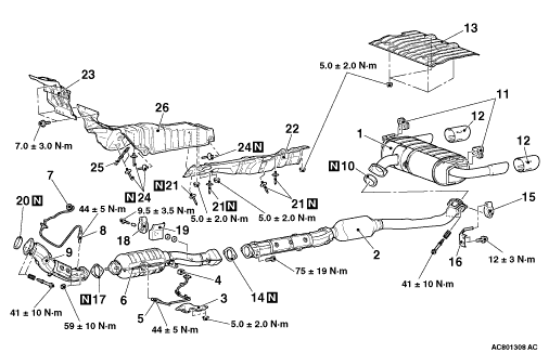
Exhaust main muffler and rear floor panel heat protector removal steps
|
|
|
1.
|
Exhaust main muffler
|
|
|
10.
|
Seal ring
|
|
|
11.
|
Exhaust muffler hanger
|
|
|
12.
|
Exhaust tail pipe diffuser
|
|
|
13.
|
Rear floor panel heat protector
|
|
|
|
Centre exhaust pipe removal steps
|
|
|
2.
|
Centre exhaust pipe
|
|
|
10.
|
Seal ring
|
|
|
14.
|
Exhaust pipe gasket
|
|
|
15.
|
Exhaust muffler hanger
|
|
|
16.
|
Exhaust pipe hanger bracket
|
|
|
|
Catalytic converter removal steps
|
|
|
3.
|
Harness cover
|
|
|
4.
|
Oxygen sensor (rear) connector connection
|
<<A>>
|
>>B<<
|
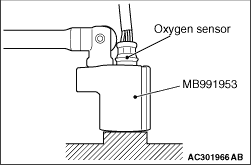
5.
|
Oxygen sensor (rear)
|
|
|
6.
|
Catalytic converter
|
|
|
14.
|
Exhaust pipe gasket
|
|
|
17.
|
Exhaust pipe gasket
|
|
|
18.
|
Exhaust muffler hanger
|
|
|
19.
|
Exhaust muffler hanger protector
|
|
|
|
Front exhaust pipe removal steps
|
|
|
·
|
Cowl side trim (Refer to GROUP 52A - Trims )
|
|
|
·
|
Footrest
|
|
|
·
|
Floor console side cover (Refer to GROUP 52A - Front Floor Console Assembly )
|
|
|
·
|
Turn up the passenger side floor carpet. <LH drive vehicles>
|
|
|
·
|
Turn up the drive’s side floor carpet. <RH drive vehicles>
|
|
|
·
|
Front floor backbone brace (Refer to GROUP 42A - Loose Panel )
|
|
|
7.
|
Oxygen sensor (front) connector connection
|
<<A>>
|
>>B<<
|
8.
|
Oxygen sensor (front)
|
|
|
9.
|
Front exhaust pipe
|
|
|
17.
|
Exhaust pipe gasket
|
|
|
20.
|
Seal ring
|
|
|
|
Front floor panel front heat protector and front floor panel rear heat protector removal steps
|
|
|
2.
|
Centre exhaust pipe
|
|
|
3.
|
Harness cover
|
|
|
4.
|
Oxygen sensor (rear) connector connection
|
|
|
6.
|
Catalytic converter
|
|
|
·
|
Cowl side trim (Refer to GROUP 52A - Trims )
|
|
|
·
|
Footrest
|
|
|
·
|
Floor console side cover (Refer to GROUP 52A - Front Floor Console Assembly )
|
|
|
·
|
Turn up the passenger side floor carpet. <LH drive vehicles>
|
|
|
·
|
Turn up the drive’s side floor carpet. <RH drive vehicles>
|
|
|
·
|
Front floor backbone brace (Refer to GROUP 42A - Loose Panel )
|
|
|
7.
|
Oxygen sensor (front) connector connection
|
|
|
9.
|
Front exhaust pipe
|
|
|
10.
|
Seal ring
|
|
|
14.
|
Exhaust pipe gasket
|
|
|
17.
|
Exhaust pipe gasket
|
|
|
20.
|
Seal ring
|
|
|
·
|
Propeller shaft assembly (Refer to GROUP 25 - Propeller Shaft )
|
<<B>>
|
>>A<<
|
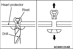
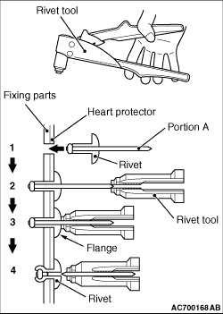
21.
|
Rivet
|
|
|
22.
|
Front floor rear panel heat protector
|
|
|
23.
|
Dash panel heat protector
|
<<B>>
|
>>A<<
|
24.
|
Rivet
|
|
|
25.
|
Oxygen sensor clip
|
|
|
26.
|
Front floor front panel heat protector
|