REMOVAL AND INSTALLATION <4B10>


Pre-removal operation
  • Engine Room Under Cover Front A, B and Engine Room Side Cover (RH) Removal (Refer to GROUP 51 - Under Cover ).
  • Radiator Condenser Tank Removal (Refer to GROUP 14 - Radiator ).
  • Alternator and Others Belt Removal (Refer to GROUP 11C - Crankshaft Pulley ).

Post-installation operation
  • Alternator and Others Belt Installation (Refer to GROUP 11C - Crankshaft Pulley ).
  • Alternator and Others Belt Tension Check (Refer to GROUP 11C - On-vehicle Service, Drive Belt Tension Check and Adjustment ).
  • Radiator Condenser Tank Installation (Refer to GROUP 14 - Radiator ).
  • Engine Room Under Cover Front A, B and Engine Room Side Cover (RH) Installation (Refer to GROUP 51 - Under Cover ).


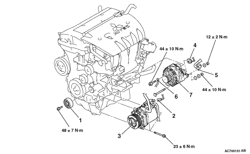
Removal steps


1.
Power steering oil pump idler pulley


2.
A/C compressor and clutch assembly connector connection
<<A>>
>>B<<
3.
A/C compressor and clutch assembly


4.
Alternator connector connection


5.
Alternator terminal connection

>>A<<
6.
Earth cable connection
<<B>>

7.
Alternator assembly

REMOVAL SERVICE POINTS


<<A>> A/C COMPRESSOR AND CLUTCH ASSEMBLY REMOVAL


1.Remove the A/C compressor and clutch assembly together with the hose from the bracket.
2.Tie the removed A/C compressor and clutch assembly with a string at a position where they will not interfere with the removal and installation of the alternator assembly.

<<B>> ALTERNATOR ASSEMBLY REMOVAL


Remove the alternator assembly to the downside.

INSTALLATION SERVICE POINTS


>>A<< EARTH CABLE CONNECTION


1.Install the earth cable in the direction shown in the illustration.
2.Tighten the alternator mounting bolt to the specified torque.
Tightening torque: 44 ± 10 N·m

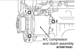
>>B<< A/C COMPRESSOR AND CLUTCH ASSEMBLY INSTALLATION


Tighten A/C compressor and clutch assembly mounting bolts to the specified torque in the order of number shown in the illustration.
Tightening torque: 23 ± 6 N·m