REMOVAL AND INSTALLATION


caution When the transmission control cable is disconnected, check after the installation that the cable is properly connected, and that the parking lock mechanism operates normally. At this time, do not check by simply using the display on the combination meter and shift indicator panel. Always check according to the procedure below.

  • With the P range, the vehicle does not move on a slight slope or when pushed by hands.
  • When driving at 5 km/h or less, the vehicle stops when the shift lever is moved to the P range.

Post-installation Operation
  • Key interlock mechanism check (Refer to .)
  • Shift lock mechanism check (Refer to .)
  • Shift lever operation check (Refer to .)


Shift lever assembly removal steps 


1.
Shift knob


·
Floor console bracket (A) (Refer to GROUP 52A - Floor Console Assembly .)

>>B<<
2.
Key interlock cable connection (shift lever side)


3.
Transmission control cable connection (shift lever side)


4.
Shift lever-ECU connector connection


5.
Shift lock solenoid connector connection


6.
Shift lever assembly


Transmission control cable removal steps (Cont.)


1.
Shift knob


·
SRS-ECU (Refer to GROUP 52B - SRS-ECU .)


·
G and yaw rate sensor and G and yaw rate sensor bracket (Refer to GROUP 35C - G and Yaw Rate Sensor .)

>>A<<
3.
Transmission control cable connection (shift lever side)


·
Air cleaner assembly (Refer to GROUP 15 - Air Cleaner .)


·
Battery (Refer to GROUP 54A - Battery .)

>>A<<
7.
Transmission control cable connection (transmission side)


8.
Transmission control cable bracket


9.
Transmission control cable

INSTALLATION SERVICE POINTS


>>A<< TRANSMISSION CONTROL CABLE (TRANSMISSION SIDE/SHIFT LEVER SIDE) INSTALLATION


1.Connect the transmission control cable (shift lever side) to the shift lever assembly.
2.Set the shift lever to the N position.

3.Operate the lever so that the shift control lever positioning mark is set to the N position.

4.Move the slider of the transmission control cable (transmission side) tip to the direction A to pull up the lock piece to the direction B.

5.Align the transmission control cable and the shift control lever joint (positioning only, do not connect), and firmly push down the lock piece to lock it. Then, connect the transmission control cable and the shift control lever.
note
  • The slider automatically returns to the fixed position by the spring.
  • The lock position of transmission control cable is automatically adjusted by a spring.

>>B<< KEY INTERLOCK CABLE INSTALLATION


caution Leave the ignition switch in the LOCK (OFF) position until the key interlock cable installation is completed.
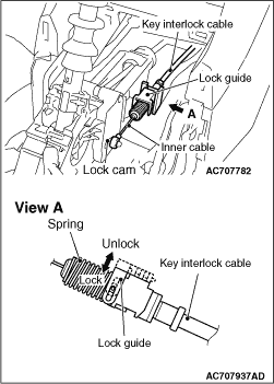
1.Move the shift lever to the P position, and turn the ignition switch to the LOCK (OFF) position.

2.Install the tip of key interlock cable to the lock cam of shift lever assembly, using a caution not to twist the inner cable.
3.Install the adjuster case with its lock guide pulled up (unlocked).
4.Firmly push down the lock guide to lock it.
note The lock position of the key interlock cable is automatically adjusted by a spring.