REMOVAL AND INSTALLATION


caution
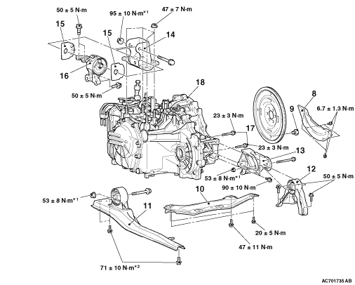
  • The part indicated by the *1 mark should be temporarily tightened, and then fully tightened with the engine and transmission assembly weight applied on the vehicle body.
  • The bolts marked with *2 are coated with the friction coefficient stabilizer. After removing these bolts, make sure that they are free of damage, remove any dust and dirt on the bearing surfaces and the threads, and then securely tighten to the specified torque.
Pre-removal and Post-installation Operation
  • Engine Room Under Cover and Engine Room Side Cover Removal and Installation (Refer to GROUP 51, Under Cover ).
  • Transmission Fluid Draining and Refilling (Refer to ).
  • Air Cleaner Assembly and Air Cleaner Bracket Removal and Installation (Refer to GROUP 15, Air Cleaner ).
  • Battery and Battery Tray Removal and Installation (Refer to GROUP 54A, Battery ).
  • Front Exhaust Pipe and Main Muffler Removal and Installation (Refer to GROUP 15, Front Exhaust Pipe and Main Muffler ).
  • Engine-ECU Removal and Installation (Refer to GROUP 13A, Engine-ECU ).
  • Engine Cover Removal and Installation (Refer to GROUP 11A, Camshaft ).
  • Starter Motor Assembly Removal and Installation (Refer to GROUP 16, Stator Motor Assembly ).
  • Drive Shaft Removal and Installation (Refer to GROUP 26, Drive Shaft Assembly .)


Removal steps


1.
A/T control solenoid valve assembly connector


2.
Input shaft speed sensor connector


3.
Output shaft speed sensor connector


4.
Cover and inhibitor switch connector

>>C<<
5.
Transmission control cable


6.
Transmission assembly upper part coupling bolt


7.
A/T fluid cooler hose assembly connection


Removal steps


8.
Bell housing cover


9.
Torque converter and drive plate coupling bolts


10.
Backbone brace


11.
Centre member assembly


12.
Rear roll stopper


13.
Transmission case rear roll stopper bracket


·
While supporting the engine and transmission assembly with a garage jack.


14.
Transmission mounting bracket

>>B<<
15.
Transmission mounting insulator stopper


16.
Transmission mounting insulator
<<A>>

·
Engine assembly supporting


17.
Transmission assembly lower part coupling bolts

>>A<<
18.
Transmission assembly

REMOVAL SERVICE POINTS


<<A>> ENGINE ASSEMBLY SUPPORTING


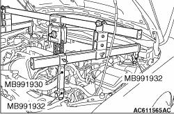
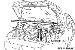
1.<When engine hanger (Special tool: MB991928) is used>
(1) Assemble the engine hanger (Special tool: MB991928). (Set the components below to the base hanger.)

  • Slide bracket (HI)
  • Foot x 4 (standard) (MB991932)
  • Joint x 2 (90) (MB991930)
(2) Set the feet of the special tool as shown in the figure.
note Adjust the engine hanger balance by sliding the slide bracket (HI).
(3) Remove the garage jack and then remove the transmission assembly upper part coupling bolts that have been loosened previously.


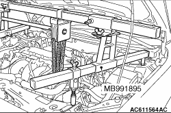
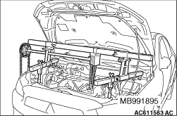
2.<When using engine mechanical hanger (Special tool: MB991895)>
(1) Set the foot of the engine mechanical hanger (Special tool: MB991895) as shown in the figure.
note Slide the front foot of the engine mechanical hanger (Special tool: MB991895) to balance the engine hanger.
(2) Remove the garage jack and then remove the transmission assembly upper part coupling bolts that have been loosened previously.

INSTALLATION SERVICE POINTS


>>A<< TRANSMISSION ASSEMBLY INSTALLATION


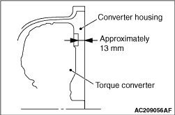
Fully push the torque converter into the transmission side, and then assemble the transmission assembly to the engine.

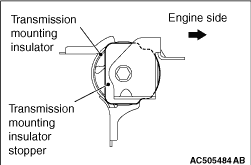
>>B<< TRANSMISSION MOUNTING INSULATOR STOPPER INSTALLATION


Install the transmission mounting insulator stopper as shown in the figure.

>>C<< TRANSMISSION CONTROL CABLE INSTALLATION


1.Move the selector lever and manual control lever to the N position.
2.Tighten the transmission control cable locking nut to the specified torque.
Tightening torque: 9.5 ± 3.5 N·m