REMOVAL AND INSTALLATION


caution
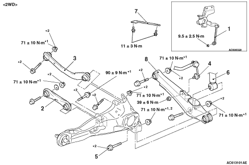
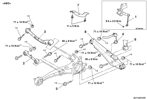
  • The parts indicated by *1 should be temporarily tightened, and then fully tightened with the vehicle standing on the ground and the curb weight condition.
  • The parts indicated by *2 are the bolts/nuts with friction coefficient stabilizer. In removal, ensure there is no damage, clean dust and soiling from the bearing and thread surfaces, and tighten them to the specified torque.
Post-installation operation
  • Using your fingers, press the Ball Joint Dust Cover to check for a crack or damage.
  • Wheel alignment check and adjustment (Refer to .)
  • Check the beam direction of the headlamp (Low beam) (Refer to GROUP 54A - Headlamp Aiming ).


Control link and upper arm removal


1.
Rear height sensor to control link connection <Vehicles with headlamp automatic levelling system>
<<A>>

2.
Control link


·
Fuel tank vapour hose connection (Refer to GROUP 13E, Fuel tank <4A9, 4B1-2WD>, <4B1-4WD>, <BWC>.)

>>A<<
3.
Upper arm


Lower arm removal steps


1.
Rear height sensor to control link connection <Vehicles with headlamp automatic levelling system>


4.
Stabilizer link connection
<<B>>

5.
Lower arm and trailing arm connection


6.
Shock absorber and lower arm connection


7.
Rear suspension crossmember stay


8.
Lower arm


Control link and upper arm removal


1.
Rear height sensor to control link connection <Vehicles with headlamp automatic levelling system>
<<A>>
>>B<<
2.
Control link


·
Fuel tank vapour hose connection (Refer to GROUP 13E, Fuel tank .)

>>A<<
3.
Upper arm


Lower arm removal steps


1.
Rear height sensor to control link connection <Vehicles with headlamp automatic levelling system>


4.
Stabilizer link connection
<<B>>

5.
Lower arm and trailing arm connection


6.
Shock absorber and lower arm connection


7.
Rear suspension crossmember stay


8.
Lower arm

REMOVAL SERVICE POINTS


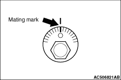
<<A>> CONTROL LINK REMOVAL


Make a mating mark on the toe adjusting bolt, and remove the control link.

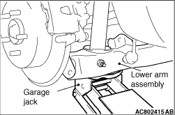
<<B>> LOWER ARM AND TRAILING ARM DISCONNECTION


While jacking-up the lower arm with garage jack, remove the mounting bolts.

INSTALLATION SERVICE POINTS


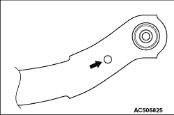
>>A<< UPPER ARM INSTALLATION


Install the upper arm so that the hole faces the body side.

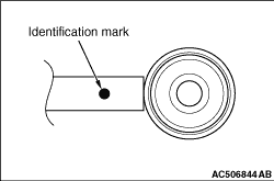
>>B<< CONTROL LINK INSTALLATION


Install the control link so that the identification mark faces the outside of the body.