|
|
- When the parking brake switch is turned ON, the combination meter terminal
No.4 is earthed, and the brake warning lamp illuminates.
- When reduction of the brake fluid amount is detected, the brake fluid level switch
is turned from ON to OFF. ETACS-ECU monitors the brake fluid level switch, and instructs the combination
meter via the CAN bus line to illuminate the brake warning lamp.
|
|
|
- The brake pad thickness is at the limit value or less.
- The brake fluid amount is at the "LOWER" level or lower.
- Poor adjustment of the parking brake lever
- Damaged wiring harness and connectors
- Parking brake switch malfunction
- Malfunction of brake fluid level switch
- Combination meter malfunction
- Malfunction of ETACS-ECU
|
|
|
Use M.U.T.-III to diagnose the CAN bus lines.
|
|
|
Q.
Is the check result normal?
|
|
|
 Repair the CAN bus lines (Refer to GROUP 54C - CAN Bus Diagnosis table Repair the CAN bus lines (Refer to GROUP 54C - CAN Bus Diagnosis table  ). ).
|
|
|
|
|
|
Use M.U.T.-III to check that the diagnosis code is set in the combination meter and ETACS-ECU.
|
|
|
Q.
Is the diagnosis code set?
|
|
|
 Carry out the diagnosis for the diagnosis code. Carry out the diagnosis for the diagnosis code.
|
|
|
|
|
|
Check that the brake fluid is filled up to the "MIN" level or higher.
|
|
|
Q.
Is the check result normal?
|
|
|
Refer to GROUP 35A - On-vehicle Service, Brake Pad Check .
|
|
|
Q.
Is the check result normal?
|
|
|
Fill the brake fluid up to the "MAX" level. Then go to Step 17.
|
|
|
|
|
|
Replace the brake pad. <Refer to GROUP 35A - On-vehicle Service,
Brake Pad Replacement (except RALLIART), (RALLIART).> Then
go to Step 17.
|
|
|
|
|
|
Refer to GROUP 35A - On-vehicle Service, Brake Fluid Level Switch Check .
|
|
|
Q.
Is the check result normal?
|
|
|
Replace the reservoir tank assembly. <Refer to GROUP 35A - Master
Cylinder Assembly · Brake Booster Assembly (except RALLIART), (RALLIART).>
Then go to Step 17.
|
|
|
|
|
|
Q.
Is the check result normal?
|
|
|
Repair the damaged connector.
|
|
|
|
|
|
(1)Disconnect the connector, and measure at the wiring harness side.
|
|
|
(2)Turn the ignition switch to the ON position.
|
|
|
(3)Measure the voltage between the terminal No. 1 and the body earth.
OK: Approximately battery voltage
|
|
|
Q.
Is the check result normal?
|
|
|
(1)Turn the ignition switch to the ON position.
|
|
|
(2)Measure the voltage between terminal No. 1 and the body earth by backprobing.
OK: Approximately battery voltage
|
|
|
Q.
Is the check result normal?
|
|
|
Check the wiring harness between the C-312 ETACS-ECU connector terminal No. 1
and the A-07 brake fluid level switch connector terminal No. 1.
|
|
|
|
|
|
Replace the ETACS-ECU. (Refer to GROUP 54A - ETACS .)
Then go to Step 17.
|
|
|
|
|
|
Check for open circuit in the harness wire between A-07 brake fluid level switch connector
terminal No. 2 and body earth.
|
|
|
Q.
Is the check result normal?
|
|
|
Repair the wiring harness.
|
|
|
|
|
|
Refer to GROUP 36 - On-vehicle Service .
|
|
|
Q.
Is the check result normal?
|
|
|
Adjust the parking brake lever stroke. (Refer to GROUP 36 - On-vehicle
Service .) Then go to Step 17.
|
|
|
|
|
|
Refer to GROUP 36 - On-vehicle Service .
|
|
|
Q.
Is the check result normal?
|
|
|
Replace the parking brake switch. (Refer to GROUP 36 - Parking Brake
Lever .) Then go to Step 17.
|
|
|
|
|
|
Q.
Is the check result normal?
|
|
|
Repair the damaged connector.
|
|
|
|
|
|
(1)Disconnect the connector, and measure at the wiring harness side.
|
|
|
(2)Turn the ignition switch to the ON position.
|
|
|
(3)Measure the voltage between the terminal No. 1 and the body earth.
OK: Approximately battery voltage
|
|
|
Q.
Is the check result normal?
|
|
|
Q.
Is the check result normal?
|
|
|
Repair the damaged connector.
|
|
|
|
|
|
(1)Release the parking brake lever (status that the lever is not operated).
|
|
|
(2)Turn the ignition switch to the ON position.
|
|
|
(3)Measure the voltage between terminal No. 4 and the body earth by backprobing without
disconnecting the connector.
OK: Approximately battery voltage
|
|
|
Q.
Is the check result normal?
|
|
|
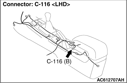
Repair the wiring harness between the C-01 combination meter connector terminal
No. 4 and the C-116 parking brake switch connector terminal No. 1.
|
|
|
|
|
|
Q.
Does the brake warning lamp turn ON and OFF normally according to the parking brake
lever operation?
|
|
|
Intermittent malfunction (Refer to GROUP 00 - How to Cope with Intermittent
Malfunction .)
|
|
|
|
|
|
Replace the combination meter assembly. (Refer to GROUP 54A - Combination
Meter .) Then go to Step 17.
|
|
|
|
|
|
Q.
Does the brake warning lamp turn ON and OFF normally according to the parking brake
lever operation?
|
|
|
This diagnosis is complete.
|
|
|
|