REMOVAL AND INSTALLATION <EXCEPT RALLIART>


<MASTER CYLINDER AND BRAKE BOOSTER>


Pre-removal operation
  • Brake Fluid Draining
  • Air Cleaner Cover Removal <LHD> (Refer to GROUP 15 - Air Cleaner <1500> <1800> or <2000> ).

Post-installation operation
  • Air Cleaner Cover Installation <LHD> (Refer to GROUP 15 - Air Cleaner <1500> <1800> or <2000> ).
  • Brake Fluid Refilling and Air Bleeding (Refer to ).
  • Clutch Fluid Supplying <RHD - M/T>
  • Clutch Bleeding <RHD - M/T> (Refer to GROUP 21A - Clutch Bleeding ).


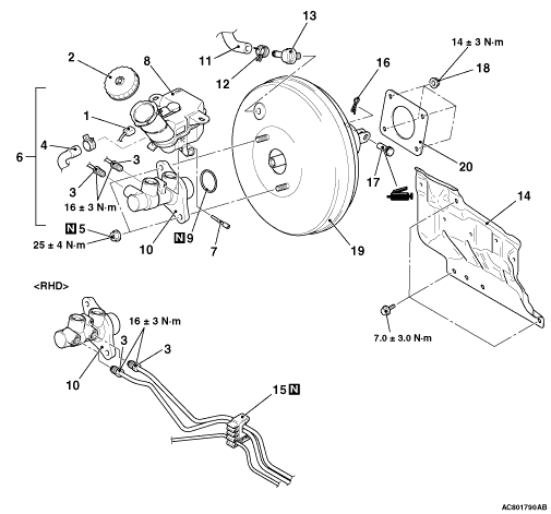
Master cylinder removal steps


1.
Brake fluid level switch connector connection


2.
Reservoir cap


3.
Brake pipe connection

>>B<<
·
Bleeding of master cylinder assembly (only at installation)


4.
Reservoir hose connection <M/T>


5.
Master cylinder mounting nuts


6.
Reservoir assembly and master cylinder assembly


7.
Torx bolt


8.
Reservoir assembly


9.
O-ring


10.
Master cylinder assembly


Brake booster removal steps


·
Clutch master cylinder <RHD - M/T> (Refer to GROUP 21A, Clutch Pedal .)


1.
Brake fluid level switch connector connection


3.
Brake pipe connection

>>B<<
·
Bleeding of master cylinder assembly (only at installation)


4.
Reservoir hose connection <M/T>


5.
Master cylinder mounting nuts


6.
Reservoir assembly and master cylinder assembly

>>A<<
11.
Vacuum hose connection


12.
Hose clip


13.
Check valve


14.
Dash panel heat protector


15.
Brake fluid line clip connection <RHD>


16.
Snap pin


17.
Pin assembly


·
Instrument panel cover lower <Vehicles with instrument panel cover lower> (Refer to GROUP 52A, Instrument Lower Panel .)


18.
Brake booster mounting nut


·
Cowl top panel (Refer to GROUP 42A, Loose Panel .)


·
Strut tower bar <Vehicles with strut tower bar> (Refer to GROUP 42A, Strut Tower Bar .)


19.
Brake booster assembly


20.
Seal

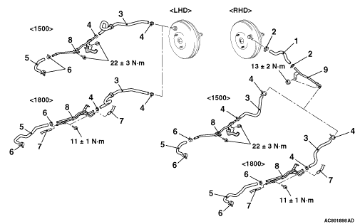
<VACUUM HOSE AND VACUUM PIPE (VEHICLES WITH PETROL ENGINE) >


Removal steps

>>A<<
1.
Vacuum hose <RHD>


2.
Hose clip <RHD>

>>A<<
3.
Vacuum hose


4.
Hose clip

>>A<<
5.
Vacuum hose


6.
Hose clip


7.
Emission vacuum hose connection <1800>


8.
Vacuum pipe assembly


9.
Vacuum pipe <RHD>

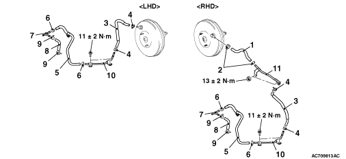
<VACUUM HOSE AND VACUUM PIPE (VEHICLES WITH DIESEL ENGINE) >


Removal steps

>>A<<
1.
Vacuum hose


2.
Hose clip

>>A<<
3.
Vacuum hose


4.
Hose clip

>>A<<
5.
Vacuum hose


6.
Hose clip


7.
Vacuum joint

>>A<<
8.
Vacuum hose


9.
Hose clip


10.
Vacuum pipe


11.
Vacuum pipe <RHD>

INSTALLATION SERVICE POINTS


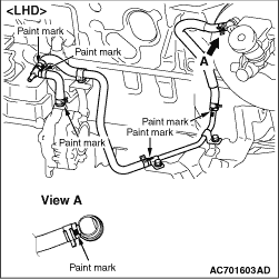
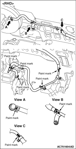
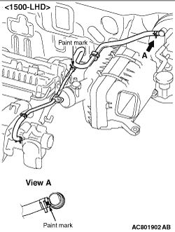
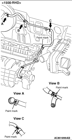
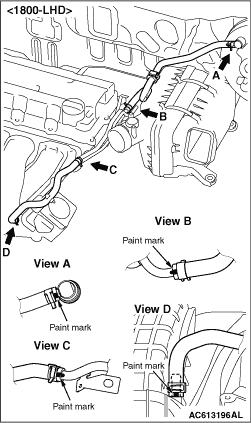
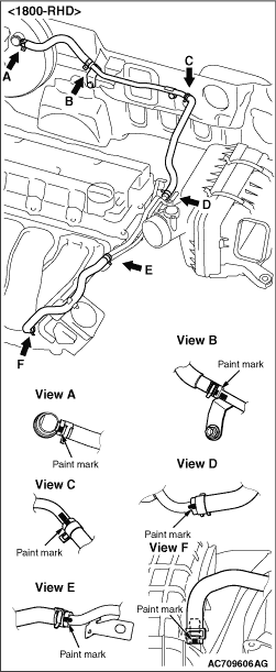
>>A<< VACUUM HOSE INSTALLATION


<Vehicles with petrol engine>
    Align the mark as shown in the figure to assemble the vacuum hose.


<Vehicles with diesel engine>
    Align the mark as shown in the figure to assemble the vacuum hose.

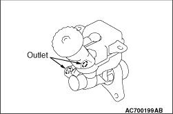
>>B<< BLEEDING OF MASTER CYLINDER ASSEMBLY


When removed the master cylinder assembly, bleed the master cylinder in the following procedure to make bleeding of the brake pipeline easier (When no brake fluid is in the master cylinder).
1.Fill the brake fluid reservoir with the brake fluid.
2.Depress and hold the brake pedal.

3.Another operator closes the master cylinder outlets with his fingers.
4.In this condition, release the brake pedal.
5.Repeat Steps 2 to 4 for 3 or 4 times to fill the master cylinder with the brake fluid.