|
|
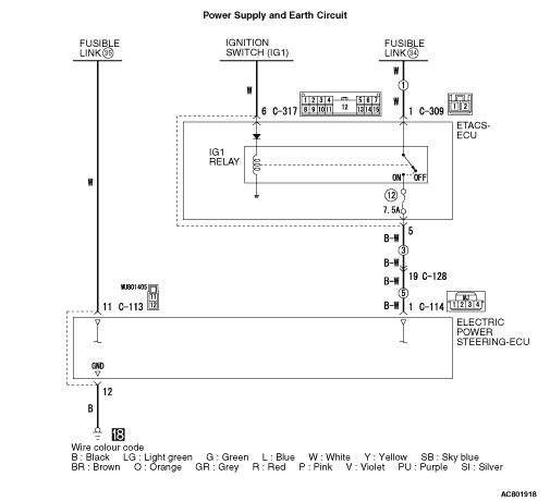
- Power is supplied to the electric power steering-ECU from the battery or the ignition switch.
|
|
|
- To control the steering gear and linkage assembly, the battery voltage is supplied to the electric power steering-ECU for energisation.
|
|
|
Check Conditions
- The ETACS power supply circuit system diagnosis code is not set.
|
|
|
Judgement Criterion
- The power supply voltage is less than 9.0 V.
- The power supply monitor voltage does not meet a predetermined voltage stored in the microcomputer, and the microcomputer determines that there is a problem in the power supply system.
|
|
|
Fail Safe, Back Up Function
- The electric power steering-ECU tapers the motor control and illuminates the electric power steering warning display, then sets the diagnosis code No. C1541.
|
|
|
- Malfunction of CAN bus line
- Defective battery
- Charging system failed
- Defective harness wire(s) or connector(s)
- Short or open circuit between the electric power steering-ECU, the ETACS-ECU and the fusible link or loose connector contact
- Open circuit between the body earth and the electric power steering-ECU or loose connector contact
- Malfunction of the ETACS-ECU
- Malfunction of the electric power steering-ECU
|
|
|
Use M.U.T.-III to diagnose the CAN bus lines.
|
|
|
Q.
Is the check result normal?
|
|
|
 Repair the CAN bus lines (Refer to GROUP 54C - Troubleshooting Repair the CAN bus lines (Refer to GROUP 54C - Troubleshooting  ).On completion, go to Step 2. ).On completion, go to Step 2.
|
|
|
|
|
|
(1)Erase the diagnosis code.
|
|
|
(2)Turn the ignition switch from the LOCK (OFF) position to the ON position.
|
|
|
(3)Check if the diagnosis code is set.
|
|
|
Q.
Is the diagnosis codes C1541 set?
|
|
|
This diagnosis is complete.
|
|
|
|
|
|
Start the engine and measure the battery voltage (Refer to GROUP 54A - Battery Test ).
|
|
|
Q.
Is the check result normal?
|
|
|
Check the battery and repair if necessary (Refer to GROUP 54A - Charging System , GROUP 54A - Removal and Installation ). Then go to Step 11.
|
|
|
|
|
|
Start the engine and measure the charging system (Refer to GROUP 16 - Charging System ).
|
|
|
Q.
Is the check result normal?
|
|
|
Check the charging system and repair if necessary (Refer to GROUP 16 - Alternator Assembly ).Then go to Step 11.
|
|
|
|
|
|
Check the connectors below for improper engagement, terminal damage or terminal drawn in the connector case.
|
|
|
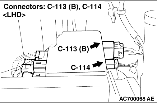
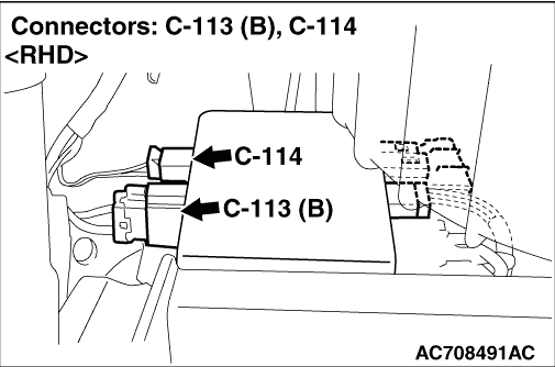
- C-113 and C-114-1 electric power steering-ECU connector
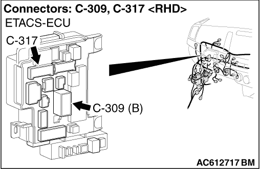
- C-309 and C-317 ETACS-ECU connector
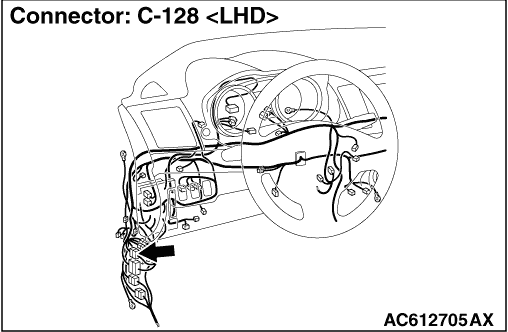
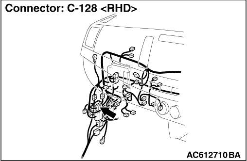
- C-128 intermediate connector
- No.34 and No.35 fusible link
- No.18 body earth point
|
|
|
Q.
Is the connectors and terminals in good condition?
|
|
|
Repair the defective connector(s) or terminal(s). Then go to Step 11.
|
|
|
|
|
|
(1)Check the wiring harness between the C-113 electric power steering-ECU connector terminal No.11 and the fusible link No.35 for damage or other problem .
|
|
|
(2)Check the wiring harness between the C-114 electric power steering-ECU connector terminal No.1, the C-128 intermediate connector terminal No.19 and the C-317 ETACS-ECU connector terminal No.5 for damage or other problem .
|
|
|
(3)Check the wiring harness between the C-309 ETACS-ECU connector terminal No.1 and the fusible link No.34 for damage or other problem .
|
|
|
(4)Check the wiring harness between the C-113 electric power steering-ECU connector terminal No.12 and the body earth point No.18 for damage or other problem .
|
|
|
Q.
Is the wiring harness in good condition?
|
|
|
Repair the defective wiring harness. Then go to Step 11.
|
|
|
|
|
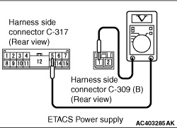
(1) Measure the ETACS-ECU voltage without disconnecting the connector (by backprobing).
(2)Turn the ignition switch from the LOCK (OFF) position to the ON position.
(3)Measure the voltage between the C-309 ETACS-ECU connector terminal No.1 and the C-317 ETACS-ECU connector terminal No.5.
OK: Approximately battery voltage
Q.
Is the check result normal?
 Go to Step 8. Go to Step 8.
Check the fusible link or the ETACS-ECU and repair if necessary(Refer to GROUP 54A-ETACS ).Then go to Step 11.
|
|
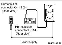
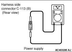
(1) Measure the electric power steering-ECU voltage without disconnecting the connector (by backprobing).
(2)Turn the ignition switch from the LOCK (OFF) position to the ON position.
(3)Measure the voltage between the C-114 electric power steering-ECU connector terminal No.1 and the C-113 electric power steering-ECU connector terminal No.12.
OK: Approximately battery voltage
(4)Measure the voltage between the C-113 electric power steering-ECU connector terminals No.11 and No.12.
OK: Approximately battery voltage
Q.
Is the check result normal?
Go to Step 9.
Check the fusible link or the ETACS-ECU and repair if necessary(Refer to GROUP 54A-ETACS ).Then go to Step 11.
|
|
|
Check the following service data .
|
|
|
- Item No. 22: Power relay voltage
|
|
|
- Item No. 23: Ignition voltage
|
|
|
Q.
Is the check result normal?
|
|
|
(1)Erase the diagnosis code.
|
|
|
(2)Turn the ignition switch from the LOCK (OFF) position to the ON position.
|
|
|
(3)Check if the diagnosis code is set.
|
|
|
Q.
Is the diagnosis codes C1541 set?
|
|
|
Replace the electric power steering-ECU (Refer to ).Then go to Step 11.
|
|
|
|
|
|
Intermittent malfunction (Refer to GROUP 00 - How to Cope with Intermittent Malfunction ).
|
|
|
|
|
|
(1)Erase the diagnosis code.
|
|
|
(2)Turn the ignition switch from the LOCK (OFF) position to the ON position.
|
|
|
(3)Check if the diagnosis code is set.
|
|
|
Q.
Is the diagnosis codes C1541 set?
|
|
|
This diagnosis is complete.
|
|
|
|